
Connecting ring automatic cap puller

A connecting ring, automatic technology, applied in the direction of metal processing, metal processing equipment, manufacturing tools, etc., to achieve the effect of long service life, fast and convenient feeding, and reliable transmission

Active Publication Date: 2017-06-30
ZHEJIANG JINRUI HARDWARE RIGGING
View PDF5 Cites 0 Cited by
  • Summary
  • Abstract
  • Description
  • Claims
  • Application Information

AI Technical Summary

Problems solved by technology

[0003] In order to solve the problem in the background technology that the existing connecting ring needs to be manually pulled to adjust the screw pitch after processing, the present invention provides an automatic connecting ring cap pulling machine

Method used


Image

  • Connecting ring automatic cap puller
  • Connecting ring automatic cap puller
  • Connecting ring automatic cap puller

Examples


Embodiment Construction

[0021] Embodiments of the present invention will be further described below in conjunction with accompanying drawings:

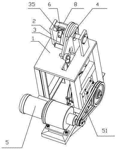
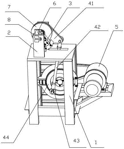
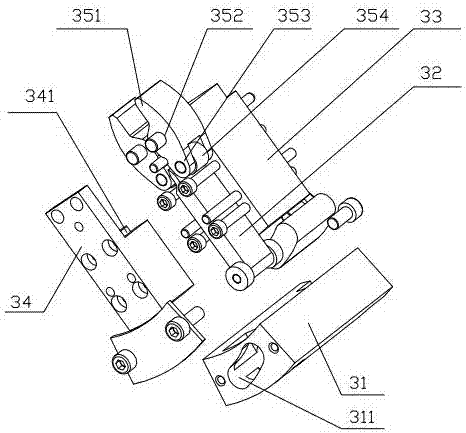
[0022] Depend on figure 1 combine figure 2 , 3 , 4, and 5, a connecting ring automatic cap puller includes a frame 1, and the frame 1 is provided with a mounting plate 2, a manipulator 3, a transmission mechanism and a driver 5, and the mounting plate 2 There is a feeding part 6 for placing the connecting ring 8 to be processed, and the feeding part 6 is provided with a feeding trough 61 for placing the connecting part 81 of the connecting ring 8 and a nut part 82 for placing the connecting ring 8. The accommodating groove 62 and the notch groove 63 that are convenient for processing, the accommodating groove 62 communicates with the feeding groove 61 and the notch groove 63 respectively, the described driving member 5 drives the manipulator 3 to swing through the transmission mechanism, and the described The manipulator 3 has a first state of clamping t...


PUM


Abstract

The invention discloses an automatic cap wrenching machine for a connection ring. The problem that in the prior art, manual cap wrenching is needed for screw pitch adjustment after the connection ring is machined is solved. The automatic cap wrenching machine comprises a rack, wherein an installation plate, a manipulator, a transmission mechanism and a driving component are arranged on the rack; a material feeding component which is used for holding the to-be-machined connection ring is arranged on the installation plate; the material feeding component is provided with a material feeding groove which is used for holding the connection part of the connection ring, an accommodation groove which is used for holding the screw cap part of the connection ring and a notch groove which facilitates machining; the accommodation groove is communicated with the material feeding groove and the notch groove; the driving component drives the manipulator to swing through the transmission mechanism; and the manipulator has a first state of clamping the screw cap part of the connection ring, a second state of driving the screw cap part of the connection ring to rotate through the driving of the transmission mechanism and a third state of idling after releasing. The automatic cap wrenching machine has the advantages of being simple in structure, reliable in transmission, low in manual cost, capable of achieving continual machining, high in machining efficiency, long in service life and the like.

Description

technical field [0001] The invention relates to a cap pulling device for a sling connecting ring, in particular to an automatic cap pulling machine for a connecting ring. Background technique [0002] The existing connecting ring usually includes a connecting part and a nut part. The connecting part is usually formed by bending a metal wire. The nut portion is usually provided with internal threads. When the connection part and the nut part are assembled for the first time, it is necessary to correct the connection part and the nut part. Usually, the manufacturer needs to turn the cap manually so that the pitch of the connection part and the nut part can be aligned. After that, the customer or user can Easily pull the cap off. Such a processing method is time-consuming and laborious, the processing intensity is high, the workers are prone to fatigue, and the efficiency is low. Contents of the invention [0003] In order to solve the problem in the background art that th...

Claims


Application Information

Patent Timeline
Patent Type & Authority Patents(China)
IPC IPC(8): B23P19/10
CPCB23P19/10
Inventor 夏建忠
Owner ZHEJIANG JINRUI HARDWARE RIGGING
Learn More