Coaxial assembly method for shaft components and coaxiality detection method for shaft components

A technology of assembly method and detection method, applied in the direction of assembly machine, measuring device, using optical device, etc., can solve the problem of inability to assist coaxial assembly and coaxiality detection, and achieve improved assembly product efficiency, high speed, and reduced processing. cost effect

Active Publication Date: 2016-03-23
LUOYANG INST OF ELECTRO OPTICAL EQUIP OF AVIC
View PDF7 Cites 11 Cited by
  • Summary
  • Abstract
  • Description
  • Claims
  • Application Information

AI Technical Summary

Problems solved by technology

This method uses an optical method to detect the verticality and position of the orthogonal mechanical shaft system of complex optoelectronic products, but it cannot assist coaxial assembly and coaxiality detection

Method used


Image

  • Coaxial assembly method for shaft components and coaxiality detection method for shaft components
  • Coaxial assembly method for shaft components and coaxiality detection method for shaft components
  • Coaxial assembly method for shaft components and coaxiality detection method for shaft components

Examples


Embodiment 1

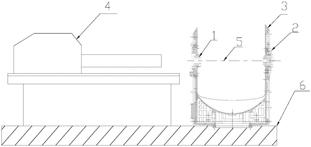
[0029] In this embodiment, the shafting parts that need to be assembled coaxially are the shafting parts at both ends of the U-shaped seat, and its structural characteristics are as follows figure 1 As shown: the two sides of the U-shaped seat 3 are the left and right half-shaft parts (denoted as the left shaft part 1 and the right shaft part 2) connected by the middle frame. First, ensure that the two shaft parts rotate coaxially, so that the middle frame can Coaxial rotation in two shaft systems.

[0030] The coaxial assembly method of shafting components in this embodiment includes the following steps:

[0031] 1) Confirm that the bearing installation shafts of the two shafting components to be coaxially assembled have process holes, and the coaxiality between the axis of the process holes and the bearing installation shaft is not greater than 0.02mm;

[0032] Such as figure 1 As shown, the inner focusing telescope 4 and the U-shaped seat 3 are placed on the fixed platfor...

Embodiment 2

[0038] In this embodiment, the shafting parts at both ends of the assembled U-shaped seat are tested. The structural characteristics of the shafting parts at both ends of the U-shaped seat are as follows: figure 1As shown: the two sides of the U-shaped seat 3 are the left and right half-shaft parts (denoted as the left shaft part 1 and the right shaft part 2) connected by the middle frame, and the two shaft parts rotate coaxially (axis 5 such as figure 1 shown), in order to make the middle frame rotate coaxially in the two shaft systems.

[0039] The method for detecting the coaxiality of shafting components in this embodiment includes the following steps:

[0040] 1) Confirm that the bearing installation shafts of the two shafting components that have been coaxially assembled have process holes, and the coaxiality between the axis of the process holes and the bearing installation shaft is not greater than 0.02mm;

[0041] Such as figure 1 As shown, the inner focusing telesc...


PUM


Abstract

The invention discloses a coaxial assembly method for shaft components and a coaxiality detection method for the shaft components. The assembly method includes the steps that a reticle is assembled into a process hole in one shaft component, and the shaft component and an internal focusing telescope are adjusted to establish a benchmark, so that the self-collimating image circle drawing amount received by the internal focusing telescope is minimum when the shaft component rotates, the position P1 of a reticle image is recorded, and the shaft component and the internal focusing telescope are fixed; and the reticle is assembled into a process hole of another shaft component, and the shaft component is adjusted, so that the self-collimating image circle drawing amount received by the internal focusing telescope is minimum when the shaft component rotates, the position P2 of a reticle image and the position P1 of the reticle image coincide with each other, and the shaft component is fixed and assembled. According to the coaxial assembly method and the coaxiality detection method, the shaft component assembly and coaxiality detection are achieved through an optical method, assembly precision is high, efficiency is high, the detection error is small, the speed is high, operation is simple, the application range is wide, and the methods are suitable for being applied and popularized.

Description

technical field [0001] The invention belongs to the technical field of precision shafting assembly, in particular to a method for coaxially assembling shafting parts, and also relates to a method for detecting the coaxiality of shafting parts. Background technique [0002] With the continuous development of optoelectronic system comprehensive technology, high-precision steady aiming technology and high-precision transmission system have become an inevitable trend of development at this stage. In order to ensure that the optoelectronic system can accurately capture, aim and track targets, the coaxial assembly of And coaxiality detection have put forward very high index requirements. In the prior art, there are mainly three methods for measuring the coaxiality of ordinary mechanical shafting components: three-coordinate measurement method, meter measurement method and the method of using a data acquisition instrument to connect a dial indicator. Due to the low precision and la...

Claims


Application Information

Patent Timeline
Patent Type & Authority Applications(China)
IPC IPC(8): B23P21/00G01B11/27
CPCB23P21/00G01B11/27
Inventor 李朋辉肖均强孔小辉
Owner LUOYANG INST OF ELECTRO OPTICAL EQUIP OF AVIC
Why Eureka
Try Eureka