
Self-unloading type material shifting and transporting hopper

A self-unloading and hopper technology, applied in the field of self-unloading material moving hoppers, can solve the problems of leakage, increase the working time, occupy the space of the barrel, and achieve good material sealing, reduce labor intensity and reliable operation. Effect

Active Publication Date: 2016-03-23
NANYANG FUSEN MAGNESIUM POWDER CO LTD
View PDF8 Cites 6 Cited by
  • Summary
  • Abstract
  • Description
  • Claims
  • Application Information

AI Technical Summary

Problems solved by technology

This utility model can automatically discharge the material under the action of gravity, but because the conical bottom plate occupies a large amount of space in the barrel, the load of the material at one time is too small, and the barrel is open up and down, during the reloading and transfer process, If the conical bottom plate tilts or vibrates slightly, it may cause material leakage
The patent application number 201520341195.6 discloses a self-unloading hopper, including a hopper, a valve stem and a flange ring arranged on the outer side of the lower part of the hopper. The lower part of the hopper is cone-shaped, and the upper part inside the hopper is Two support rods with the same specifications are arranged parallel to the lower position, and each of the two support rods is provided with a guide sleeve at the midpoint position, and the valve stem passes through the two guide sleeves, and is set at the tail of the valve stem. There is a valve plate, and a lifting lug is set on the top of the valve stem. When the valve plate and the flange ring are closed, it just seals the bottom of the hopper. This utility model has fast feeding, high temperature operation, and reliable operation. Strict, to avoid material leakage, the bottom of the utility model uses the valve plate and the flange ring for airtight cooperation, but the area of ​​the valve plate is too large, the material will be affected when it falls, and the working time will be increased

Method used


Image

  • Self-unloading type material shifting and transporting hopper
  • Self-unloading type material shifting and transporting hopper
  • Self-unloading type material shifting and transporting hopper

Examples


Embodiment 1

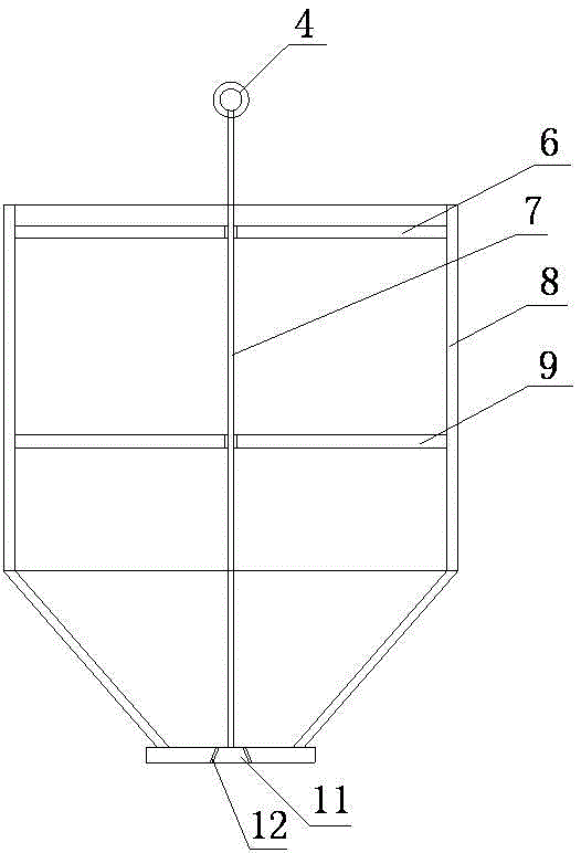
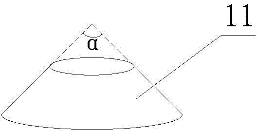
[0022] refer to Figure 1~Figure 2 , a self-unloading material transfer hopper of the present invention, comprising a hopper 8 with a tapered lower part, a guide bracket is arranged inside the hopper 8, a boom 7 is movable through the center of the guide bracket, and a suspension ring is arranged at the top of the boom 7 4. A plug 11 is provided at the lower end, and a frustum-shaped through hole 12 is provided on the bottom plate of the hopper 8 , and the plug 11 cooperates with the frustum-shaped through hole 12 to realize the sealing of the hopper 8 .

[0023] In this embodiment, the lower part of the hopper 8 is a conical structure, the upper part is a cylindrical structure, and the upper part has an opening for charging.

[0024] There are 2 groups of guide brackets, which are respectively the first guide bracket 6 and the second guide bracket 9, which are respectively arranged at the opening and the middle part of the hopper 8, and have the functions of wearing and suppo...

Embodiment 2

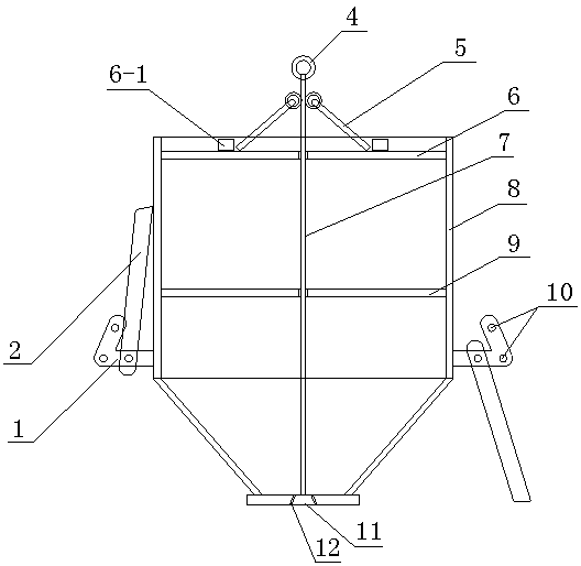
[0029] refer to Figure 3~Figure 4 , a self-unloading material transfer hopper of the present invention, comprising a hopper 8 with a tapered lower part, a guide bracket is arranged inside the hopper 8, a boom 7 is movable through the center of the guide bracket, and a suspension ring is arranged at the top of the boom 7 4. A plug 11 is provided at the lower end, and a frustum-shaped through hole 12 is provided on the bottom plate of the hopper 8 , and the plug 11 cooperates with the frustum-shaped through hole 12 to realize the sealing of the hopper 8 .

[0030] The self-unloading material transfer hopper 8 described in this embodiment is different from Embodiment 1 in that:

[0031] There are 3~4 sets of support assemblies on the side of the hopper 8. The support assemblies are composed of a support 1 and a leg 2 hingedly connected to it. The support 1 is provided with upper and lower limit pins 10; the guide bracket is provided with a stopper 6-1 , the top of the suspender...

Embodiment 3

[0035] See 5~ Figure 6 , a self-unloading material transfer hopper of the present invention, comprising a hopper 8 with a tapered lower part, a guide bracket is arranged inside the hopper 8, a boom 7 is movable through the center of the guide bracket, and a suspension ring is arranged at the top of the boom 7 4. A plug 11 is provided at the lower end, and a frustum-shaped through hole 12 is provided on the bottom plate of the hopper 8 , and the plug 11 cooperates with the frustum-shaped through hole 12 to realize the sealing of the hopper 8 .

[0036] The self-unloading material transfer hopper 8 described in this embodiment is different from Embodiment 2 in that:

[0037] The upper part of the hopper 8 is provided with auxiliary hooks 3, and the number of auxiliary hooks 3 is 2 to 4, which are evenly arranged on the outer side of the upper part of the hopper 8. The plug 11 is conical, and the degree of the cone angle of the plug 11 is greater than or equal to 150o and Less ...


PUM

PropertyMeasurementUnit
Degreeaaaaaaaaaa
Degreeaaaaaaaaaa

Abstract

The invention provides a self-unloading type material shifting and transporting hopper and belongs to the technical field of material storage or transportation devices. The self-unloading type material shifting and transporting hopper comprises a hopper body with the lower portion of a conical structure. A guide support is arranged in the hopper body. A suspension rod penetrates the center of the guide support movably. A suspension ring is arranged at the top end of the suspension rod, and a plug is arranged at the lower end of the suspension rod. A frustum-shaped through hole is formed in a base plate of the hopper body, and the plug is matched with the frustum-shaped through hole so as to seal the hopper body. The self-unloading type material shifting and transporting hopper is novel in structure and reasonable in design; and by researching the falling character of materials, the hopper is subjected to a series of structural improvements in consideration of material airtightness, operation convenience, operation efficiency and the like of the hopper, so that loading and unloading are more convenient, the material airtightness is better, operation is safer and more reliable, the operation efficiency is improved, and the labor intensity is relieved.

Description

technical field [0001] The invention belongs to the technical field of material storage or transportation devices, and in particular relates to a self-unloading material transfer hopper. Background technique [0002] As an auxiliary equipment in the conveying system, the hopper plays the role of connecting and coordinating the crane and the belt conveyor system. Usually, the hopper works by relying on the self-weight of the material without power. Its working condition mainly depends on the physical characteristics of the material and the geometry of the hopper. The working condition of the hopper here mainly refers to the flow condition of the material when it is discharged from the discharge port. There are two most common flow conditions, one is the so-called "vertical column flow", the material above the discharge port moves vertically, the material near the bucket wall is stationary or flows slowly, and the center of the upper surface of the material sinks to form a fun...

Claims


Application Information

Patent Timeline
IPC IPC(8): B65D90/00B65D90/54B65D90/66
CPCB65D90/0033B65D90/545B65D90/66
Inventor 曹长城
Owner NANYANG FUSEN MAGNESIUM POWDER CO LTD
Learn More