Conveying and grabbing integrated device for paint

A paint and conveyor belt technology, applied in the field of charging devices, can solve the problems of complex device structure, increased difficulty, difficult control of conveyor belts and material grabbing devices, etc., and achieves the effect of reducing matching difficulty, easier control, and space saving.

Pending Publication Date: 2016-03-23
CHONGQING HENGO SCHILLER DECORATION ENG CO LTD
View PDF0 Cites 4 Cited by
  • Summary
  • Abstract
  • Description
  • Claims
  • Application Information

AI Technical Summary

Problems solved by technology

[0007] In the above operations, to control the stepping motor, it is necessary to connect the control program, through which the stepping motor rotates intermittently; and when the grabbing device swings to feed at a certain angle, it is also necessary to connect the grabbing device to another stepping motor. The stepper motor is also controlled by the control program to swing intermittently; the structure of the whole device becomes more complicated, which makes it difficult to control the conveyor belt and the grabbing device, and the conveyor belt and the grabbing device are separate structures, which need to be controlled separately by the control system , which increases the difficulty of the coordination of the two

Method used


Image

  • Conveying and grabbing integrated device for paint

Examples


Embodiment Construction

[0023] The present invention will be described in further detail below by means of specific embodiments:

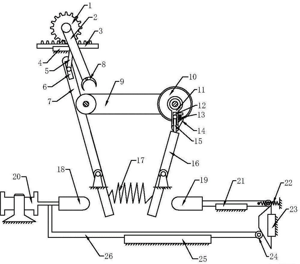
[0024] The reference signs in the drawings of the description include: gear 1, connecting rod 2, rack 3, fixed chute 4, pull rod 5, second chute 6, second swing rod 7, claw 8, belt conveyor 9 , ratchet 10, rotating rod 11, first chute 12, first spring 13, pawl 14, connecting rod 15, first swing lever 16, second spring 17, second push block 18, first push block 19, Cylinder 20, the 3rd chute 21, the 3rd spring 22, the 4th chute 23, roller 24, the 5th chute 25, push rod 26.

[0025] Example basic reference figure 1 As shown: the integrated device for transporting and grasping materials for paint, including a belt conveyor 9 and claws 8, the claws 8 are arranged above the belt conveyor 9, and a ratchet 10 is connected to the driving wheel of the belt conveyor 9, The axis of the driving wheel is provided with a main shaft, and the ratchet 10 is connected with a flat key on ...


PUM


Abstract

The invention discloses a conveying and grabbing integrated device for paint. The conveying and grabbing integrated device comprises a conveying belt and a gripper arm. A ratchet wheel is connected to the conveying belt. A first swing rod is arranged below the ratchet wheel and provided with a rotary rod. The first swing rod is in sliding connection with the rotary rod, and the rotary rod is hinged to a pawl. The pawl is connected with a first elastic piece. A second swing rod is arranged at the left side of the first swing rod, and a second elastic piece is arranged between the two swing rods. A fixed sliding groove is formed above the second swing rod. A rack is arranged in the fixed sliding groove. A pull rod is hinged to the rack. The pull rod is in sliding connection with the second swing rod. The rack is meshed with a gear. The gripper arm is connected to the gear. A first push block is arranged at the right side of the first swing rod. A second push block is arranged at the left side of the second swing rod. The second push block is connected with an air cylinder and a push rod. Rolling wheels are arranged at the right end of the push rod and the right end of the first push block, the two rolling wheels abut against the same wedge block, and the first push block is connected with a third elastic piece. According to the device, by means of air cylinder control and the arrangement of a connected structure, the structure is simplified, and coordinating difficulty is lowered.

Description

technical field [0001] The invention relates to a charging device, in particular to an integrated device for conveying and grasping materials for paint. Background technique [0002] Paint is a liquid organic compound that can harden and form a solid when it is applied to the surface of an object for protection and decoration. Paint is commonly referred to as coating. Paint consists of binders, pigments and solvents, and sometimes various additives can be added according to the requirements of use. [0003] Resins are commonly used as binders for paints, including shellac, linseed oil, alkyds, formaldehydes, polyesters, acrylics, epoxies, polyurethanes, vinyls, rubber derivatives and asphalt etc. Alkyd binders are commonly used in construction and ship coatings; polyester binders are generally used in wood finishing and enameled wire paints; acrylic and polyurethane resins are mostly used in motor and aircraft coatings; epoxy resins are used in steel Primer of components...

Claims


Application Information

Patent Timeline
Patent Type & Authority Applications(China)
IPC IPC(8): B65G23/40B65G47/90
Inventor 朱森忠
Owner CHONGQING HENGO SCHILLER DECORATION ENG CO LTD
Why Eureka
Try Eureka