Magnetic pump

A magnetic pump and pump cover technology, applied to pumps, pump devices, pump components, etc., can solve problems such as overheating of the pump shaft, demagnetization of internal magnetic components, and melting of plastic parts

Inactive Publication Date: 2016-03-23
ZHENJIANG GREAT PUMP
View PDF6 Cites 3 Cited by
  • Summary
  • Abstract
  • Description
  • Claims
  • Application Information

AI Technical Summary

Problems solved by technology

After the medium is evacuated, the internal magnetic assembly that continues to idle drives the pump shaft to continuously generate sliding friction with the bearing seat. The rotation and friction of the sliding bearing generate a lot of heat that cannot be taken away in time due to the lack of cooling of the flowing working medium, and due to the pump shaft Due to the manufacturing materials and other reasons, the overheating of the pump shaft or the demagnetization of the internal magnetic components or the melting of the plastic parts

Method used


Image

  • Magnetic pump

Examples


specific Embodiment approach

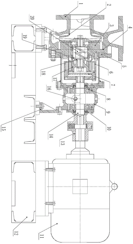
[0015] Examples such as figure 1 As shown, a magnetic pump includes a pump body 1, an impeller 2, a pump cover 3, a gasket 4, a bracket 5, an outer magnetic rotor component 6, a shielding sleeve 7, a bearing 8, a bearing housing 9, a bearing gland 10, Motor 11, base 12, claw type coupling 13, right shaft 14, foot 15, oil mirror 16, inner magnetic rotor part 17, thrust plate 18, pressure plate 19 and left shaft 20; the pump body 1 is fixedly installed on the base 12 and close to the left side of the base 12, the impeller 2 is fixed on the left side of the left shaft 20 by screws, the pump cover 3 is installed in the mounting hole at the right end of the pump body 1, the pump cover 3 and the pump body 1 A sealing gasket 4 is installed on the contact surface between the two, the bracket 5 is fixedly installed on the right side of the pump cover 3, and the inner magnetic rotor part 17 is fixedly installed on the left shaft 29 through screws and gaskets. On the right end face, the...


PUM


Abstract

The invention discloses a magnetic pump which is mainly characterized in that a pump body is mounted on a base; an impeller is mounted on the left side surface of a left rotating shaft; a pump cover is mounted in a mounting hole in the right end of the pump body; a bracket is mounted on the right side surface of the pump cover; an internal magnet rotor component is mounted on the right end surface of the left rotating shaft; the left rotating shaft is mounted in a centrale hole of in the pump cover; a pressing plate is mounted on the right side surface of the pump cover; a thrust disc is mounted on the left rotating shaft; a shielding sleeve is fixedly mounted on the right end surface of the pump cover; an external magnet rotor component is mounted on a right rotating shaft; the left side surface of a bearing housing is mounted on the right side surface of the bracket; a left side bearing gland is mounted on the left side surface of the bearing housing; a left side bearing is mounted at the left end of the right rotating shaft; a right side bearing gland is mounted on the right side surface of the bearing housing; a right side bearing is mounted at the right end of the right rotating shaft; an oil lens is mounted on the bearing housing; the right end of the right rotating shaft is connected with the output shaft of a motor through a claw type coupler; the motor is fixedly mounted on the base; the bearing housing is mounted on the base through a support leg.

Description

technical field [0001] The present invention relates to the technical field of magnetic pumps, in particular to a magnetic pump. Background technique [0002] The magnetic pump (that is, the magnetic drive pump) is mainly composed of several parts such as the pump casing, the spacer sleeve, the inner magnetic assembly, the pump shaft, the impeller, and the bearing. The magnetic pump is composed of an outer magnetic assembly, an inner magnetic assembly and a non-magnetic isolation sleeve. When the external driving force drives the outer magnetic assembly to rotate, the magnetic field can penetrate the air gap and non-magnetic substances, and drive the inner magnetic assembly connected to the impeller to operate. The synchronous rotation realizes the non-contact synchronous transmission of power, and transforms the dynamic sealing structure that is easy to leak into a static sealing structure with zero leakage. Since the pump shaft and internal magnetic components are complet...

Claims


Application Information

Patent Timeline
Patent Type & Authority Applications(China)
IPC IPC(8): F04D13/06F04D29/046F04D29/08
CPCF04D13/06F04D29/046F04D29/086F05D2260/404
Inventor 袁丹青丛小青
Owner ZHENJIANG GREAT PUMP
Why Eureka
Try Eureka