Compact shelf driving device

A transmission device and compact rack technology, applied in the field of compact racks, can solve problems such as unreasonable transmission coordination, poor transmission stability of the transmission shaft, and large hand shaking force, etc., to achieve a reasonable coordination transmission mode, stable operation, and strong load capacity. Effect

Inactive Publication Date: 2016-03-23
JIANGXI ZHUOER METAL EQUIP GROUP
View PDF5 Cites 3 Cited by
  • Summary
  • Abstract
  • Description
  • Claims
  • Application Information

AI Technical Summary

Problems solved by technology

[0002] The transmission mechanism of the bottom frame of the existing compact shelf is not only relatively complex in structure, but also its transmission and matching methods are not reasonable. For example, the structure of the transmission shaft of the transmission mechanism and the transmission and cooperation methods with the corresponding matching component bushings are all traditional. The circular transmission shaft and the shaft sleeve of the seamless steel pipe are matched. The most prominent disadvantage of this matching structure and the corresponding transmission mode is that the compact rack is in the operation process due to the small frictional force of the mutual contact, and the transmission stability of the transmission shaft is poor. The force needs to be large, usually above 8N, and the coupling drive shaft and the corresponding bushing will slip after running for a long time or with a slightly larger load, resulting in idling and causing the transmission to fail

Method used


Image

  • Compact shelf driving device

Examples


Embodiment Construction

[0009] In order to further understand the technical solutions of the present invention, the present invention will be further described by the following embodiments in conjunction with the accompanying drawings.

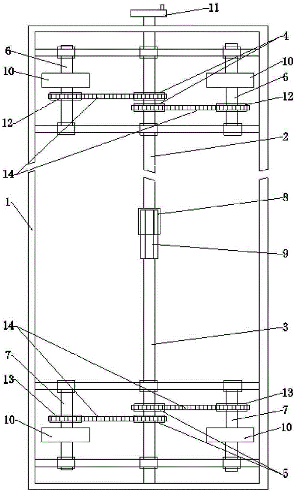
[0010] like figure 1 As shown, the compact rack transmission device of the present embodiment comprises a driving shaft 2 and a corresponding driven shaft 3 positioned on the chassis 1 of the compact rack, and two driving gears 4 and 4 are connected to the driving shaft 2 and the driven shaft 3 respectively. Two driven gears 5, and the corresponding road wheels etc. which are movably connected to the underframe 1 respectively.

[0011] The driving shaft 2 and the driven shaft 3 are respectively arranged on opposite ends of the chassis 1 through corresponding bearing devices; the outer end of the driving shaft 2 near the chassis is connected with a driving wheel 11, and the opposite ends of the driving shaft 2 and the driven shaft 3 The ends are respectively connecte...


PUM


Abstract

The invention discloses a compact shelf driving device. The compact shelf driving device comprises a driving shaft, a driven shaft and corresponding driving gear and driven gear, wherein the driving shaft and the driven shaft are respectively arranged on a compact bottom shelf; the driving gear and the driven gear are respectively connected to the driving shaft and the driven shaft; the corresponding end of the driving shaft is connected with a shaft sleeve of which the cross section is polygonal in shape; the corresponding end of the driven shaft is provided with a corresponding prism which is correspondingly matched with the shaft sleeve, wherein the cross section of the prism is polygonal in shape; the driving shaft is connected with the driven shaft by the shaft sleeve of the driving shaft and the prism of the driven shaft. The compact shelf driving device is simple in composition and structure, reasonably matched with a transmission structure, stable and reliable in transmission and high in transmission efficiency.

Description

technical field [0001] The invention relates to a compact shelf. In particular, it relates to a compact rack transmission device. Background technique [0002] The transmission mechanism of the bottom frame of the existing compact shelf is not only relatively complex in structure, but also its transmission and matching methods are not reasonable. For example, the structure of the transmission shaft of the transmission mechanism and the transmission and cooperation methods with the corresponding matching component bushings are all traditional. The circular transmission shaft and the shaft sleeve of the seamless steel pipe are matched. The most prominent disadvantage of this matching structure and the corresponding transmission mode is that the compact rack is in the operation process due to the small frictional force of the mutual contact, and the transmission stability of the transmission shaft is poor. The force needs to be large, usually more than 8N, and after a long tim...

Claims


Application Information

Patent Timeline
Patent Type & Authority Applications(China)
IPC IPC(8): F16H37/12
CPCF16H37/12
Inventor 聂建春黄贵清
Owner JIANGXI ZHUOER METAL EQUIP GROUP
Why Eureka
Try Eureka