
Diaphragm valve

A technology of diaphragm valves and diaphragms, which is applied in the direction of diaphragm valves, diaphragms, valve devices, etc., and can solve problems such as non-replacement

Active Publication Date: 2019-07-12
FESTO AG & CO KG
View PDF7 Cites 0 Cited by
  • Summary
  • Abstract
  • Description
  • Claims
  • Application Information

AI Technical Summary

Problems solved by technology

But it is not possible to replace this diaphragm in case of failure
Therefore the entire valve body unit must be replaced

Method used


Image

  • Diaphragm valve
  • Diaphragm valve
  • Diaphragm valve

Examples


Embodiment Construction

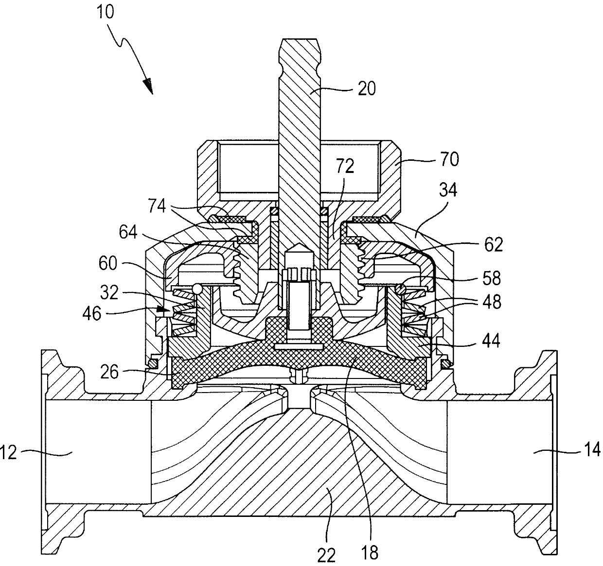
[0024] exist figure 1 The reference symbol 10 denotes a diaphragm valve which has an inlet 12 and an outlet 14 and through which a fluid flows. Inlet 12 and outlet 14 are shown as examples only. Between the inlet 12 and the outlet 14 is located a valve web 16 onto which a membrane 18 can be pushed. The diaphragm 18 is moved in an axial direction by a spindle 20 (which itself is driven by a pneumatic or electric drive not shown) between an open position in which it holds the valve and a closed position. In the open (as shown) or in this closed position, the membrane 18 pushes against the valve web 16 .

[0025] The diaphragm valve 10 has a housing lower part 22 in which the valve web 16 is located and which is open around the valve web 16 so that the fluid at the inlet 12 can flow through the outlet 14 . In the direction past the valve web 16 . The valve web 16 is surrounded by a receptacle 24 in which the membrane 18 is mounted, which is seated with its surrounding edge 26...


PUM


Abstract

The invention relates to a diaphragm valve having a a valve body housing lower part, one secured to the lower housing portion the upper housing part, one cooperating with the valve body membrane, connected to the diaphragm, axially adjustable spindle and a to the membrane a pressure-exerting thrust piece, wherein the lower housing part a is extending in the direction of the housing top pot having in which the membrane is housed, and the housing upper part is mounted in or on the pot, being provided in the upper housing part a acting on the edge of the membrane and urgent in the direction of the housing lower part pressure element.

Description

technical field [0001] The invention relates to a diaphragm valve, which has: a housing lower part with a valve body; a housing upper part fixed at the lower part of the housing; a diaphragm working together with the valve body; an axial valve connected with the diaphragm a movable spindle; and a pusher that applies pressure to the diaphragm. Background technique [0002] Membrane valves are known, the valve body of which has an inflow and an outflow. Between the inflow and the outflow, a sealing region with a valve web is located, which is sealed off by a diaphragm, wherein the diaphragm is connected to the thrust piece of the drive. A diaphragm is known from DE 10 2008 045 857 A1, the peripheral edge of which is clamped between a valve body and an intermediate piece between the valve body and the driver. It is considered problematic that the membrane loosens at high operating temperatures. Thereafter, the outward tightness of the diaphragm is no longer guaranteed, so th...

Claims


Application Information

Patent Timeline
Patent Type & Authority Patents(China)
IPC IPC(8): F16K7/16
CPCF16K7/126F16K27/0236
Inventor A.格尔布曼M.坎塔克
Owner FESTO AG & CO KG
Learn More