Quickly maintain the wiring structure of the power supply compartment of the led lamp

A technology of LED lamps and quick maintenance, applied in the direction of light source, circuit layout, components of lighting devices, etc., can solve the problems of unsatisfactory secondary installation effect, waste of manpower and material resources, and complicated maintenance operation, so as to avoid the reduction of sealing effect. , saving manpower, good versatility

Active Publication Date: 2019-03-29
西安锐泽克斯光电科技有限公司
View PDF14 Cites 0 Cited by
  • Summary
  • Abstract
  • Description
  • Claims
  • Application Information

AI Technical Summary

Problems solved by technology

In this way, the maintenance operation is complicated, and professional reinstallation is usually required, and the effect of the second installation may not be ideal
Therefore, in practice, some users will request to replace the entire lamp, which causes a waste of manpower and material resources to a certain extent.

Method used


Image

  • Quickly maintain the wiring structure of the power supply compartment of the led lamp
  • Quickly maintain the wiring structure of the power supply compartment of the led lamp
  • Quickly maintain the wiring structure of the power supply compartment of the led lamp

Examples


Embodiment Construction

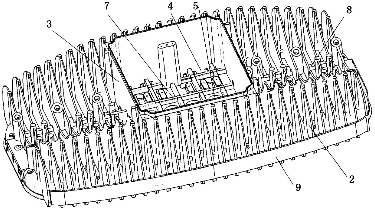
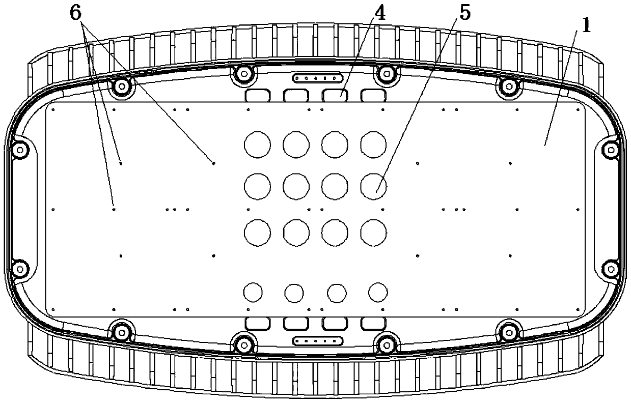
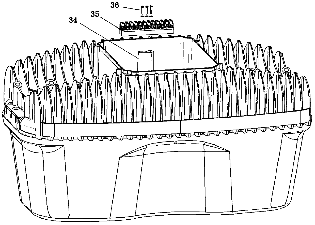
[0034] Such as Figure 1 to Figure 3 As shown, a flat-plate mounting structure is arranged on the front of the heat dissipation housing, and one or more LED chip mounting substrates are fixedly arranged on the front of the mounting structure, the power supply compartment is located on the back of the mounting structure, and the periphery of the power supply compartment is distributed There are multiple rows of heat dissipation fins; the projection positions of the power supply compartment and the LED chip mounting substrate on the mounting structure are staggered from each other, and a wiring hole is opened through the bottom of the power supply compartment, and the lines on the LED chip mounting substrate pass through the wiring holes Introduce the power supply compartment; in the power supply compartment, there is a fixed column near the side wall of the power supply compartment, and a terminal board is arranged on the upper end of the fixed column. There are several terminal...


PUM


Abstract

The invention provides a power supply bin wiring structure for maintaining an LED lamp rapidly. By the adoption of the power supply bin wiring structure, a user can replace a power supply module and conduct other operation by himself / herself conveniently, and the adaptability of the lamp is improved. According to the power supply bin wiring structure, a flat plate type installation structural component is arranged on the front portion of a heat dissipation shell; a power supply bin is located on the back side of the installation structural component, and a plurality of rows of heat dissipation fins are distributed on the periphery of the power bin; the projection positions, on the installation structural component, of the power supply bin and an LED chip installation substrate fixed to the front side of the installation structural component are staggered from each other; wiring holes are formed in the bottom surface of the power supply bin in a penetrating mode, and circuits on the LED chip installation substrate are introduced into the power supply bin through the wiring holes; a fixed column is arranged in the power supply bin and is close to the side wall of the power supply bin; a wiring plate is arranged at the upper end of the fixed column, and a plurality of wiring terminals are arranged on the wiring plate; one part of the wiring terminals are connected with input wires, and the other part of the wiring terminals are connected with output wires.

Description

technical field [0001] The invention relates to a wiring structure of a power supply compartment of an LED lamp. Background technique [0002] With the popularity of high-power LED lamps, issues such as power supply reliability, applicability, and heat dissipation need to be comprehensively considered in design. At present, the back of the heat dissipation housing of common high-power LED lamps will be provided with multiple rows of heat dissipation fins, the front of the heat dissipation housing will be provided with a mounting structure, and one or more LED chip mounting substrates will be fixed on the front of the mounting structure ( A single headlight is usually a LED chip mounting substrate, which is located in the middle of the front; a double headlight is usually two LED chip mounting substrates, which are located on the two wings of the front), and a power supply compartment is recessed in other positions on the front (for a single headlight, usually adjacent to LE...

Claims


Application Information

Patent Timeline
Patent Type & Authority Patents(China)
IPC IPC(8): F21V23/00F21V29/76F21V29/83F21V31/00F21Y115/10
CPCF21V23/002F21V31/005
Inventor 胡家培胡民海
Owner 西安锐泽克斯光电科技有限公司
Why Eureka
Try Eureka