High-power LED lamp integrated cooling shell

A heat dissipation shell and LED lamp technology, which is applied in lighting and heating equipment, semiconductor devices of light-emitting elements, cooling/heating devices of lighting devices, etc., can solve the problems of increased product weight, unfavorable wiring, and difficult molding, etc., to achieve Reduce product weight, avoid warping phenomenon, simple and beautiful appearance

Active Publication Date: 2019-01-18
西安锐泽克斯光电科技有限公司
View PDF7 Cites 0 Cited by
  • Summary
  • Abstract
  • Description
  • Claims
  • Application Information

AI Technical Summary

Problems solved by technology

[0003] The heat dissipation shell and its installation structure are usually formed by die-casting process. According to the current structure, when the size of the heat dissipation shell needs to be enlarged to meet the high power demand, after the die-casting is completed, there will be obvious warping in the length direction, which will affect the subsequent shaping process. Inconvenience, and the scrap rate will increase, which will greatly increase the cost
However, if the thickness is simply increased, the internal stress in the die-casting process will increase proportionally, making molding difficult, and the product weight will increase significantly
[0004] Moreover, such an installation structure restricts the installation layout of LED chips, leaving very limited installation space for the power supply compartment, and is not conducive to wiring
Moreover, the power module of high-power LED lamps is more prone to failure than the LED chip, and the current structure is not conducive to the maintenance of the power supply.
[0005] In addition, in recent years, many occasions have put forward the demand for intelligent management of high-power lighting equipment (such as street lamps, etc.). According to such an installation structure, the size of the power supply compartment cannot be installed with more electronic modules, and usually can only be installed in the power supply compartment. For a power supply, other electronic modules have to be separated from the LED lamp body and fixed separately for line connection

Method used


Image

  • High-power LED lamp integrated cooling shell
  • High-power LED lamp integrated cooling shell
  • High-power LED lamp integrated cooling shell

Examples


Embodiment Construction

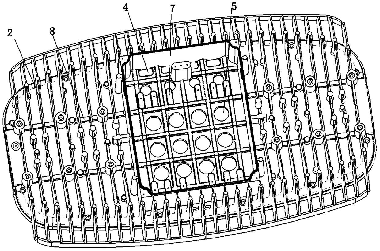
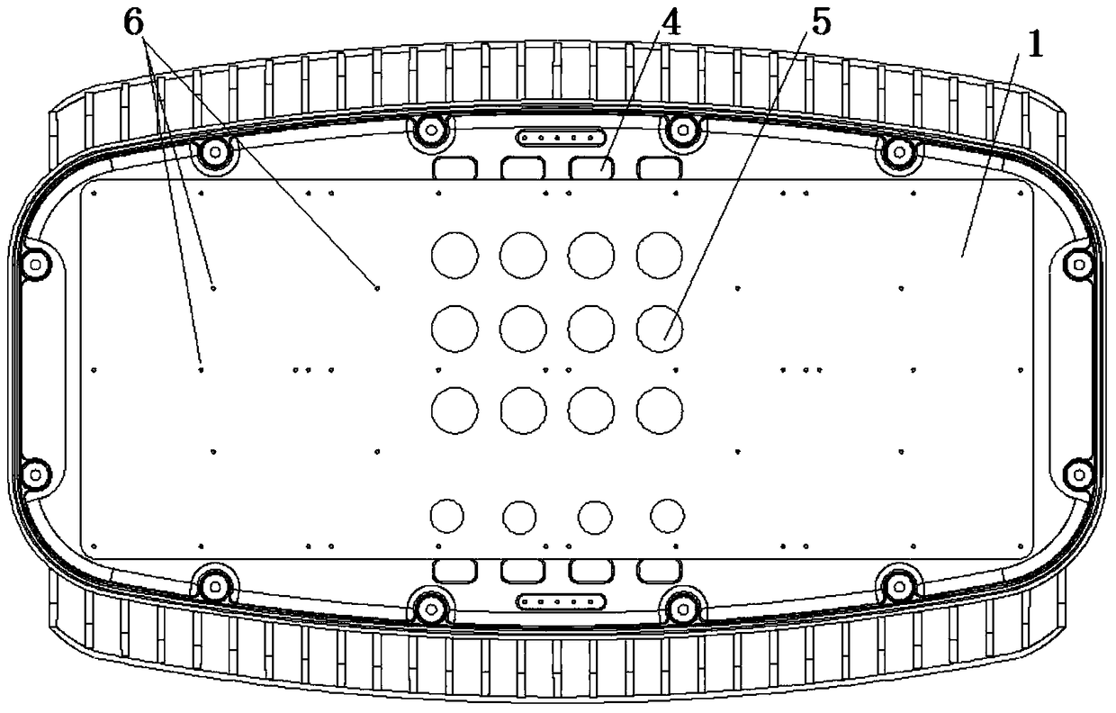
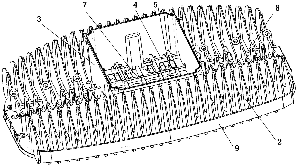
[0027] Such as Figure 1 to Figure 3 As shown, the high-power LED lamp has an integrated heat dissipation shell, and the back of the heat dissipation shell is provided with multiple rows of heat dissipation fins, and the heat dissipation fins are perpendicular to the length direction of the heat dissipation shell and parallel to the width direction of the heat dissipation shell; The front part is provided with a flat-plate mounting structure, and a plurality of reinforcing ribs are provided along the length direction on the back of the entire mounting structure (radiating fins are naturally used as reinforcing ribs in the width direction).

[0028] The power supply compartment and one or more LED chip mounting substrates are respectively fixed on the back and front of the mounting structure, and the projection positions of the power supply compartment and the LED chip mounting substrate on the mounting structure are staggered; correspondingly, on the back of the heat dissipatio...


PUM


Abstract

The invention provides a comprehensive heat dissipation shell of a high-power LED lamp. Compared with a large-size heat dissipation shell, the flatness of an installation structural component can be guaranteed, the strength of cooling fins is improved to a certain extent, and meanwhile a good heat dissipation effect is achieved. According to the comprehensive heat dissipation shell of the high-power LED lamp, a plurality of rows of cooling fins are arranged on the back of the heat dissipation shell, and the cooling fins are perpendicular to the length direction of the heat dissipation shell and parallel to the width direction of the heat dissipation shell; the flat plate type installation structural component is arranged on the front portion of the heat dissipation shell, and a plurality of reinforcing ribs are arranged on the back side of the whole installation structural component in the length direction; a power supply bin and one or more LED chip installation substrate are fixedly arranged on the back side and the front side of the installation structural component respectively; the projection positions, on the installation structural component, of the power supply bin and the LED chip installation substrate are staggered from each other; wiring holes are formed in the bottom surface of the power supply bin in a penetrating mode, and circuits on the LED chip installation substrate are introduced into the power supply bin through the wiring holes.

Description

technical field [0001] The invention relates to a heat dissipation shell of a high-power LED lamp. Background technique [0002] With the popularity of high-power LED lamps, issues such as power supply reliability, applicability, and heat dissipation need to be comprehensively considered in design. At present, the back of the heat dissipation housing of common high-power LED lamps will be provided with multiple rows of heat dissipation fins, the front of the heat dissipation housing will be provided with a mounting structure, and one or more LED chip mounting substrates will be fixed on the front of the mounting structure ( A single headlight is usually a LED chip mounting substrate, which is located in the middle of the front; a double headlight is usually two LED chip mounting substrates, which are located on the two wings of the front), and a power supply compartment is recessed in other positions on the front (for a single headlight, usually adjacent to LED chip mountin...

Claims


Application Information

Patent Timeline
Patent Type & Authority Patents(China)
IPC IPC(8): F21V29/76F21V29/83F21V19/00F21V23/00F21Y115/10
CPCF21V19/001F21V23/002
Inventor 胡家培胡民海
Owner 西安锐泽克斯光电科技有限公司
Why Eureka
Try Eureka