Electric fan heater

A fan and electric heating technology, used in electric heating systems, space heating and ventilation, household heating, etc., can solve the problems of low thermal efficiency of heating components, reduced indoor oxygen, and large power consumption, and achieve strong heating effect. , the power consumption is small, the effect of increasing the contact area

Active Publication Date: 2016-03-23
于瑶
View PDF7 Cites 0 Cited by
  • Summary
  • Abstract
  • Description
  • Claims
  • Application Information

AI Technical Summary

Problems solved by technology

[0002] As we all know, with the increase of income level, people have higher requirements for heating methods in winter, and hope to enjoy relatively fast and pollution-free heating methods. It will reduce the amount of indoor oxygen and cause air pollution at the same time. At the same time, the original heaters are gradually eliminated. People begin to care about the heating method that protects the environment and is convenient and convenient. Therefore, the demand for electric heaters is increasing.
[0003] With the needs of such consumers, electric heaters have the advantages of low price of heat source, convenient heating, and small air pollution. The ceramic heating element that generates heat, and the carbon rod heating element that uses the resistance of the carbon rod to generate heat, etc., these mainly use the resistance heat (Joule heating) generated by the resistance to disturb the current to heat the air to adjust the temperature. Most of the heat-generating components in the market introduce current into the hot wire in the form of a coil, and use resistance to generate heat. However, the thermal efficiency of such heat-generating components is generally not high, and there is generally a problem of excessive power consumption.

Method used


Image

  • Electric fan heater
  • Electric fan heater
  • Electric fan heater

Examples


Embodiment Construction

[0020] Below in conjunction with accompanying drawing, the present invention is further described:

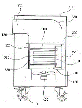
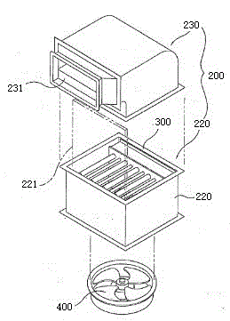
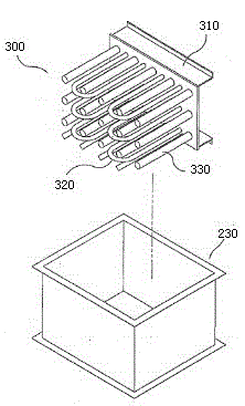
[0021] As shown in the drawings, an electric heater is provided with a box body 100, an air inlet 120 is provided at the lower end of the rear side of the box body 100, an air outlet 130 is provided at the upper end of the front side of the box body 100, and an air outlet 130 is provided at the bottom of the box body 100. The casters 110 that can move, the structure of the above-mentioned components and the interconnection between them are the same as the prior art, so I won’t repeat them here. The pipe box 200 composed of pipes 230, the lower end of the heating body 220 in the pipe box 200 is provided with an air supply device 400, the air supply device 400 is connected with an external power supply through a wire, and the air supply device 400 passes the external air through the box body 100 The air inlet 120 at the lower end and the air inlet 210 on the heating body 220 in t...


PUM


Abstract

The invention relates to the technical field of heating machinery, particularly to an electric fan heater. The electric fan heater is provided with a box, and is characterized in that a pipeline box composed of a heating machine body and an air discharging pipe is arranged in the box; an air supplying device is arranged at the lower end of the heating machine body in the pipeline box; the air discharging pipe is arranged at the upper end of the heating machine body; heating plates are arranged on the inner side surfaces of the heating machine body; fixing holes with penetrating hole structures are formed in the heating plates at equal intervals; U-shaped heating bodies are arranged on the fixing holes; heat dissipation rods are arranged among the interspace of the heating bodies; a copper heat dissipation plate is arranged on the inner wall, surrounding the heating bodies and the heat dissipation rods, of the heating machine body; the air supplying device sucks external air into the heating machine body; the air is heated through the heat emitted by the U-shaped heating bodies, heat emitted by the heat dissipation rods receiving heat of the heating bodies, and heat emitted by the copper heat dissipation plate in the heating machine body; and the heated air is discharged through the air discharging pipe. The electric fan heater has the advantages of being low in power consumption, high in heating efficiency, economic and practical to use, and the like.

Description

technical field [0001] The invention relates to the technical field of heating machinery, in particular to an economical and applicable electric heater with low power consumption and high heating efficiency. Background technique [0002] As we all know, with the increase of income level, people have higher requirements for heating methods in winter, and hope to enjoy relatively fast and pollution-free heating methods. It will reduce the amount of indoor oxygen and cause air pollution at the same time. At the same time, the original heaters are gradually eliminated. People begin to care about environmental protection and convenient heating methods, so the demand for electric heaters is increasing. [0003] With the needs of such consumers, electric heaters have the advantages of low price of heat source, convenient heating, and small air pollution. The ceramic heating element that generates heat, and the carbon rod heating element that uses the resistance of the carbon rod t...

Claims


Application Information

Patent Timeline
IPC IPC(8): F24D13/00
CPCF24D13/00
Inventor 郑东润
Owner 于瑶
Why Eureka
Try Eureka