Air-out cylinder assembly, and air sterilizer and humidifier including same

A punching bag and component technology, which is applied in air humidification system, lighting and heating equipment, space heating and ventilation, etc. It can solve the problems that affect the service life of devices, short circuit or corrosion, air leakage, etc., and achieve the effect of providing service life

Active Publication Date: 2016-03-23
GD MIDEA ENVIRONMENT APPLIANCES MFG +1
View PDF7 Cites 0 Cited by
  • Summary
  • Abstract
  • Description
  • Claims
  • Application Information

AI Technical Summary

Problems solved by technology

However, when not in use, other indoor pollutants can enter the interior of the shell from the nozzle, causing pollution to various internal structures. These pollutions will not only affect the effect of air purification, disinfection and humidification, but also affect the service life of the entire device
[0003] For movable nozzles, the tightness of the structure, the direction of the air injection

Method used


Image

  • Air-out cylinder assembly, and air sterilizer and humidifier including same
  • Air-out cylinder assembly, and air sterilizer and humidifier including same
  • Air-out cylinder assembly, and air sterilizer and humidifier including same

Examples


Embodiment 1

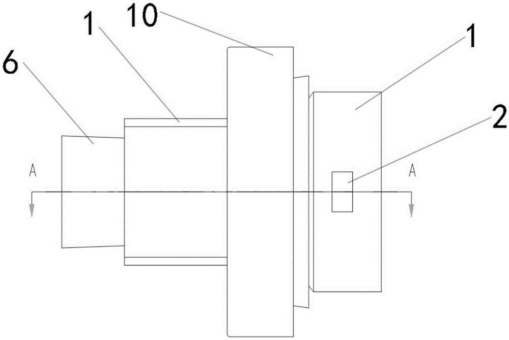
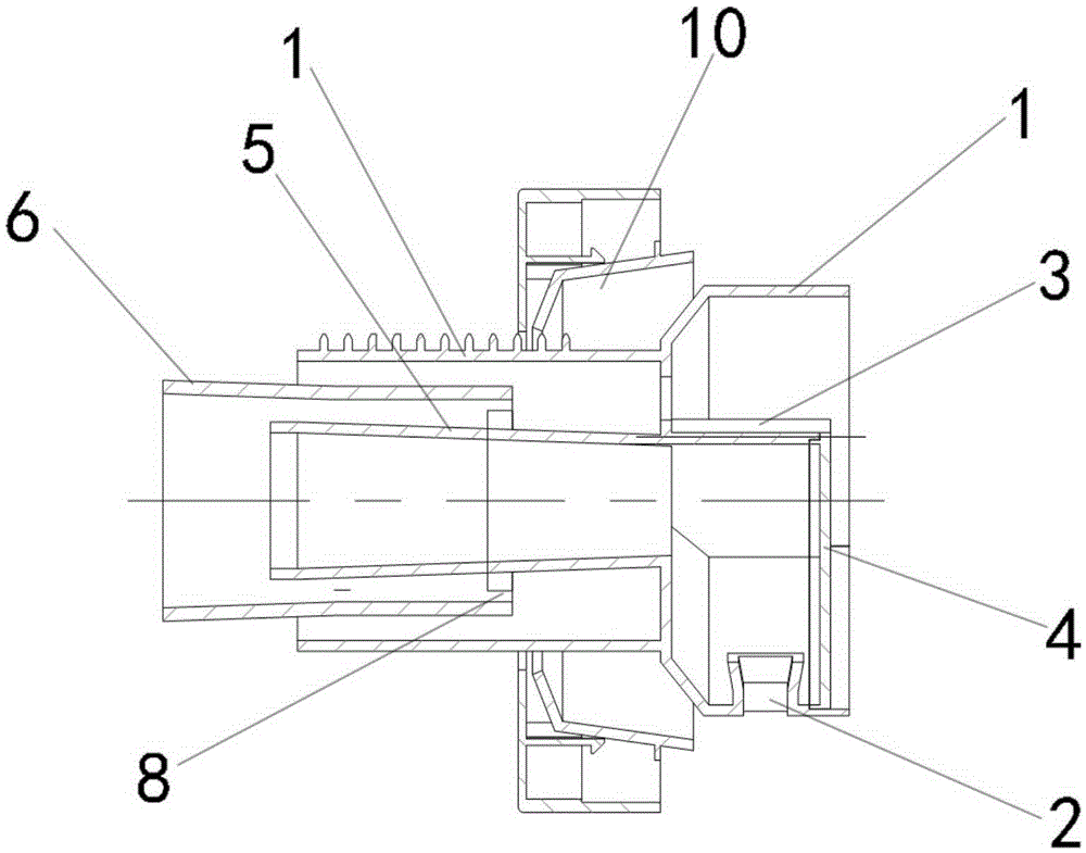
[0033] Such as figure 1 , figure 2 , Figure 5 As shown, the present invention relates to a punching bag assembly, which includes a punching bag 1 and a spray head 2 arranged at one end of the punching bag 1. The punching bag 1 is formed by connecting a large cylinder and a small cylinder coaxially, and the large cylinder is arranged radially The baffle plate 3 is divided into an air injection area and a reserved area. The spray head 2 is arranged on the circumferential side wall of the large cylinder and communicates with the air injection area. The end of the air injection area away from the small cylinder is sealed by a sealing cover 4. The small cylinder is provided with a connecting cylinder 5, one end of the connecting cylinder 5 is fixedly connected to the large cylinder and communicates with the air injection area, and the other end of the connecting cylinder 5 extends into the fixed cylinder 6 and is slidably connected with it. Near the punching bag 1, there is als...

Embodiment 2

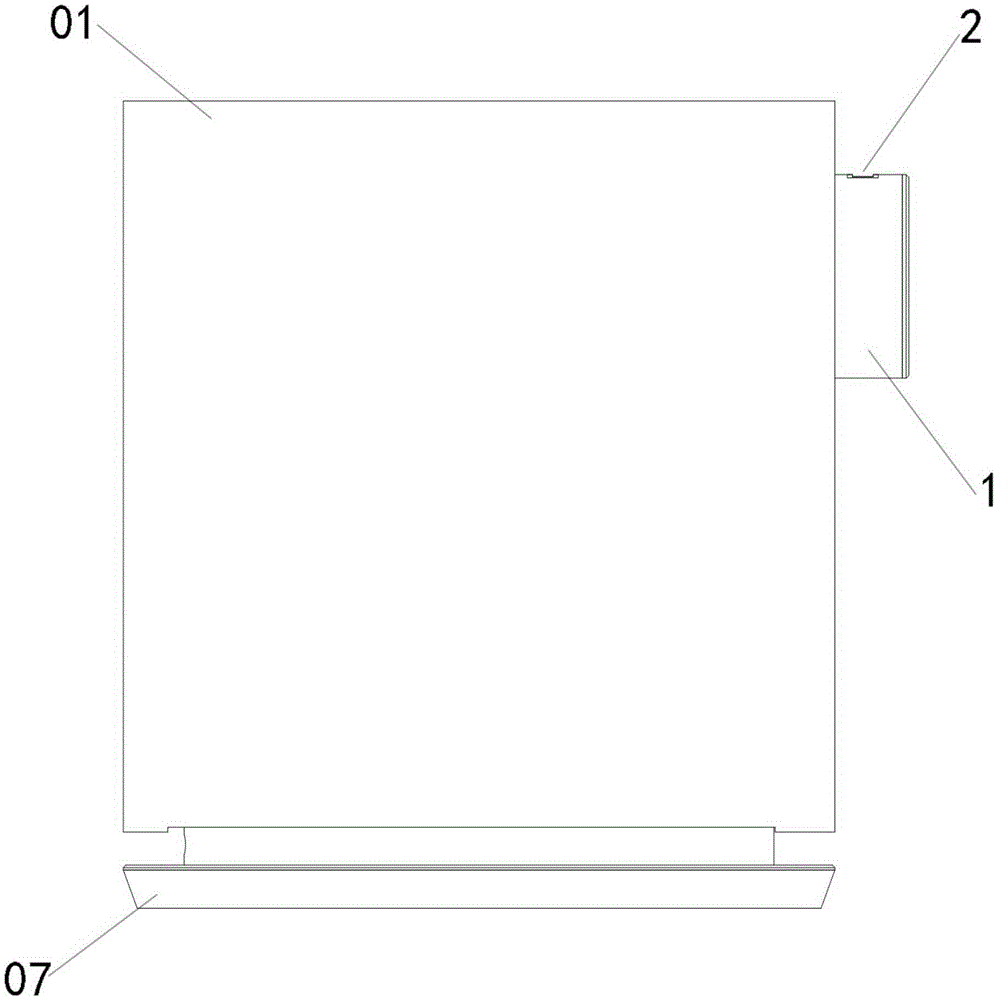
[0043] Such as Figure 3 to Figure 5As shown, the present invention relates to an air sterilizer, comprising a casing 01 and a water tank 02, an electrolytic tube 03, and an atomizer 04 that are arranged in the casing 01 and communicated in sequence, and also include the air outlet assembly, and the fixed cylinder 6 One end away from the connecting cylinder 5 is fixed to the atomizer 04 and communicates with it internally. The spray head propulsion mechanism 7 can drive the outlet bag 1 to move back and forth, so that the spray head 2 protrudes out of the housing 01 or retracts into the housing 01 .

Embodiment 3

[0045] The present invention relates to a humidifier, which includes a casing 01, a water tank 02 and an atomizer 04 arranged in the casing 01 and communicated in sequence, and also includes the outlet cylinder assembly, and the fixing cylinder 6 is fixed at one end away from the connecting cylinder 5 To the atomizer 04 and communicate with it internally. The spray head propulsion mechanism 7 can drive the outlet bag 1 to move back and forth, so that the spray head 2 protrudes out of the housing 01 or retracts into the housing 01 .

[0046] In the above-mentioned air sterilizer and humidifier, a fan 05 is provided on the side of the atomizer 04 relative to the outlet tube 1, a base 07 for supporting is also provided at the bottom of the housing 01, and a base for supporting is provided on the side wall of the atomizer 04. The circuit control board 08 that controls the operation of the humidifier.


PUM


Abstract

The invention relates to an air-out cylinder assembly, and an air sterilizer and a humidifier including the air-out cylinder assembly. The air-out cylinder assembly comprises an air-out cylinder and a nozzle arranged on one end of the air-out cylinder. The air-out cylinder is formed by connecting a large cylinder and a small cylinder in a coaxial manner. The large cylinder is divided into an air blowing region and a reserve region. The nozzle is communicated with the air blowing region. The small cylinder is internally provided with a connecting cylinder. One end of the connecting cylinder is communicated with the air blowing region, and the other end of the connecting cylinder extends into a fixing cylinder and is slidably connected with the fixing cylinder. A nozzle feed mechanism which can drive the air-out cylinder move back and forth is arranged close to the air-out cylinder. When the nozzle feed mechanism drives the air-out cylinder to move to a use state, full-sealed gas channel of the fixing cylinder, the connecting cylinder, the air blowing region, and the nozzle is formed in the air-out cylinder, and the gas channel meets gas channel leakproofness requirement in air blowing. The gas channel is fully sealed and air leakage phenomenon would not occur, thereby preventing influence of water vapor on each component in the device, and prolonging service life.

Description

technical field [0001] The invention relates to a punching bag assembly, an air sterilizer and a humidifier containing the same, and belongs to the field of air disinfection and humidification. Background technique [0002] In existing air sterilizers and humidifiers, the nozzles are all arranged on the end face of the housing, and after the nozzles are turned on to enter the working state, the airflow is directly ejected from the nozzles. However, when not in use, other pollutants in the room can enter the interior of the shell from the nozzle, causing pollution to various internal structures. These pollutions will not only affect the effect of air purification, disinfection and humidification, but also affect the service life of the entire device. [0003] For movable nozzles, the tightness of the structure, the direction of the air injection, and the amount of air injection need to be strictly controlled. If the outlet is simply set to be movable, the seal between the out...

Claims


Application Information

Patent Timeline
IPC IPC(8): F24F6/14A61L9/14F24F13/00B05B1/02
CPCA61L9/14B05B1/02F24F6/14F24F13/00
Inventor 万明
Owner GD MIDEA ENVIRONMENT APPLIANCES MFG
Why Eureka
Try Eureka