
Underground heat storage tank

A heat storage tank and underground technology, which is used in heat storage equipment, energy storage, indirect heat exchangers, etc., can solve the problems of affecting the service life of the heat storage tank, large heat loss of the heat storage tank, and easy to be eroded by wind and sand. , to achieve the effect of reducing costs and expenses, reducing maintenance costs and facilitating system operation

Inactive Publication Date: 2016-03-23
JOIN GREEN ENERGY TECH TIANJIN CO LTD
View PDF5 Cites 1 Cited by
  • Summary
  • Abstract
  • Description
  • Claims
  • Application Information

AI Technical Summary

Problems solved by technology

[0002] Heat storage tanks are usually installed on the ground, but in the field of solar power generation, the heat storage tanks we use will be exposed to the ground for a long time, and there will be many problems, such as: the heat storage tank has a large heat loss, and is susceptible to wind and sand. erosion
The combination of these factors will affect the service life of the heat storage tank, which will increase the operating cost

Method used


Image

  • Underground heat storage tank
  • Underground heat storage tank

Examples


Embodiment

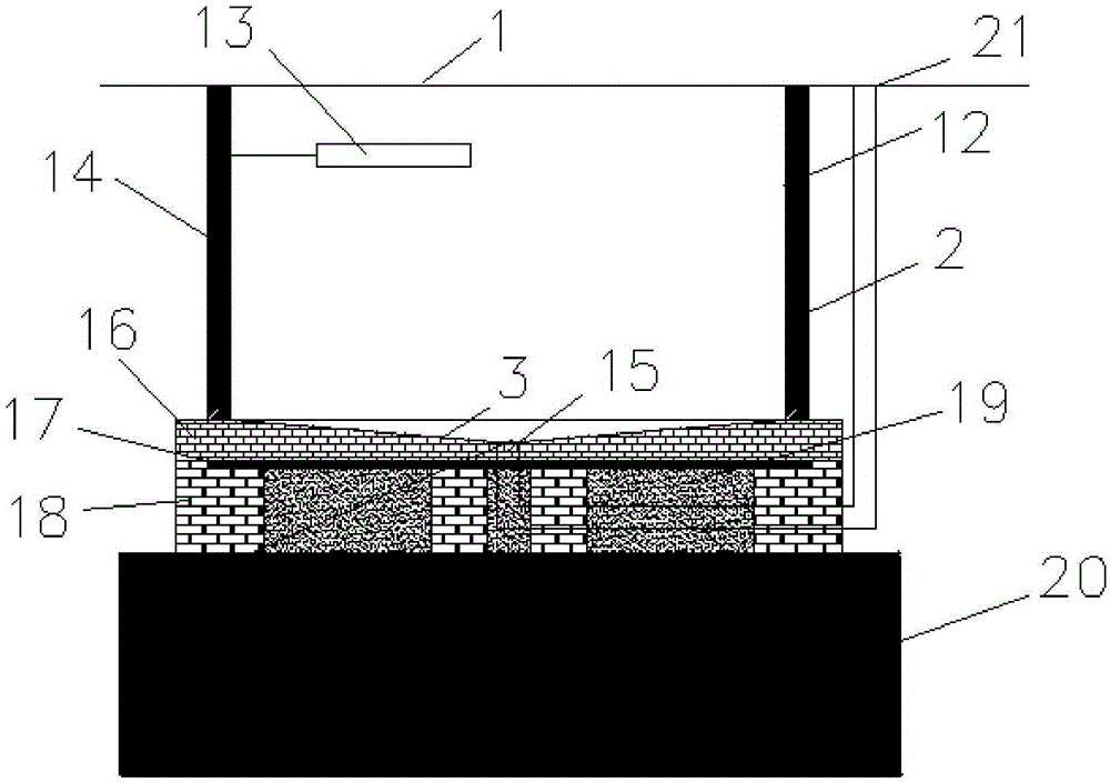
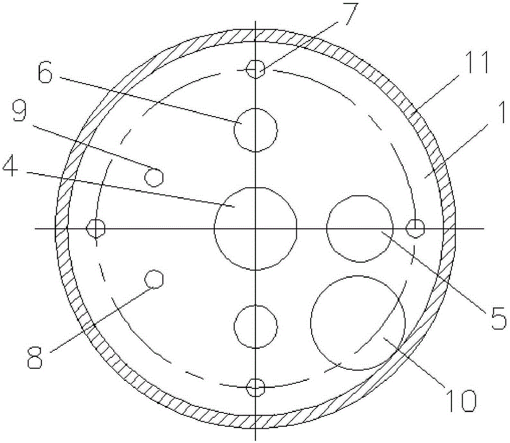
[0029] A buried heat storage tank, comprising a tank top cover 1, a tank wall 2 and a tank bottom 3, characterized in that the tank top cover 1 is provided with a molten salt pump port 4, a molten salt inlet 5, and a molten salt stirrer Port 6, electric heater port 7, liquid level gauge 8, thermometer 9, maintenance manhole 10, insulation layer A11;

[0030] The molten salt pump port 4 is located at the center of the tank top cover 1;

[0031] The molten salt stirrer port 6 is located on the longitudinal axis of the coordinate axis with the molten salt pump port 4 as the center, and is located above and below the molten salt pump port 4;

[0032] The electric heater port 7 is provided with 4, respectively located on the vertical and horizontal axes of the coordinate axis with the molten salt pump port 4 as the center of the circle, and is closest to the tank top cover 1;

[0033] The molten salt inlet 5 is located on the positive axis of the horizontal axis of the coordinate ...


PUM


Abstract

The invention relates to the field of heat energy technical equipment, in particular to an underground heat storage tank which comprises a tank top cover (1), a tank wall (2) and a tank bottom (3). The underground heat storage tank is characterized in that a molten salt pump hole (4), a molten salt inlet (5), a molten salt stirrer hole (6), an electric heater hole (7), a level gauge (8), a thermometer (9), a maintenance manhole (10) and an insulating layer A (11) are arranged on the tank top cover (1); an electric heating layer (12) and a temperature sensor (13) are arranged on the inner side of the tank wall (2); and an insulating layer B (14) is arranged at the outer part of the tank wall (2). According to the underground heat storage tank provided by the invention, a heat storage device is prevented from losing overmuch heat energy by being arranged in the atmosphere environment, a tank body can be prevented from being eroded by natural disasters including blown sand, the service life of the heat storage tank is prolonged and the changing cost and expense are lowered.

Description

technical field [0001] The invention relates to the field of thermal energy technical equipment, in particular to an underground heat storage tank. Background technique [0002] Heat storage tanks are usually installed on the ground, but in the field of solar power generation, the heat storage tanks we use will be exposed to the ground for a long time, and there will be many problems, such as: the heat storage tank has a large heat loss, and is susceptible to wind and sand. erosion. The combination of these factors will affect the service life of the heat storage tank, which will increase the operating cost. Contents of the invention [0003] Aiming at the technical problems existing in the above-mentioned prior art, the present invention aims to provide an underground heat storage tank. [0004] In order to achieve this technical purpose, the solution of the present invention is: an underground heat storage tank, including a tank top cover 1, a tank wall 2 and a tank bo...

Claims


Application Information

Patent Timeline
IPC IPC(8): F28D20/00
CPCF28D20/0043F28D2020/0047F28D2020/0065Y02E60/14Y02E70/30
Inventor 晏强
Owner JOIN GREEN ENERGY TECH TIANJIN CO LTD
Learn More