
Negative-pressure rapid butting device for sample feeding of micro-fluidic chip

A technology of microfluidic chip and docking device, which is applied in the direction of analyzing materials and instruments, and can solve the problems that gas path joints cannot be realized, and achieve high sealing performance and improve sealing performance

Active Publication Date: 2016-03-23
SUZHOU INST OF BIOMEDICAL ENG & TECH CHINESE ACADEMY OF SCI
View PDF6 Cites 4 Cited by
  • Summary
  • Abstract
  • Description
  • Claims
  • Application Information

AI Technical Summary

Problems solved by technology

[0005] Due to the characteristics of the disposable microfluidic chip, which can be inserted and used, and taken out after use, the main body of the instrument needs to frequently connect and withdraw negative pressure to the microfluidic chip, and it is also necessary to maintain airtightness during the entire detection process to prevent Pressure drop during the detection process, commonly used gas line joints, etc. cannot achieve this function

Method used

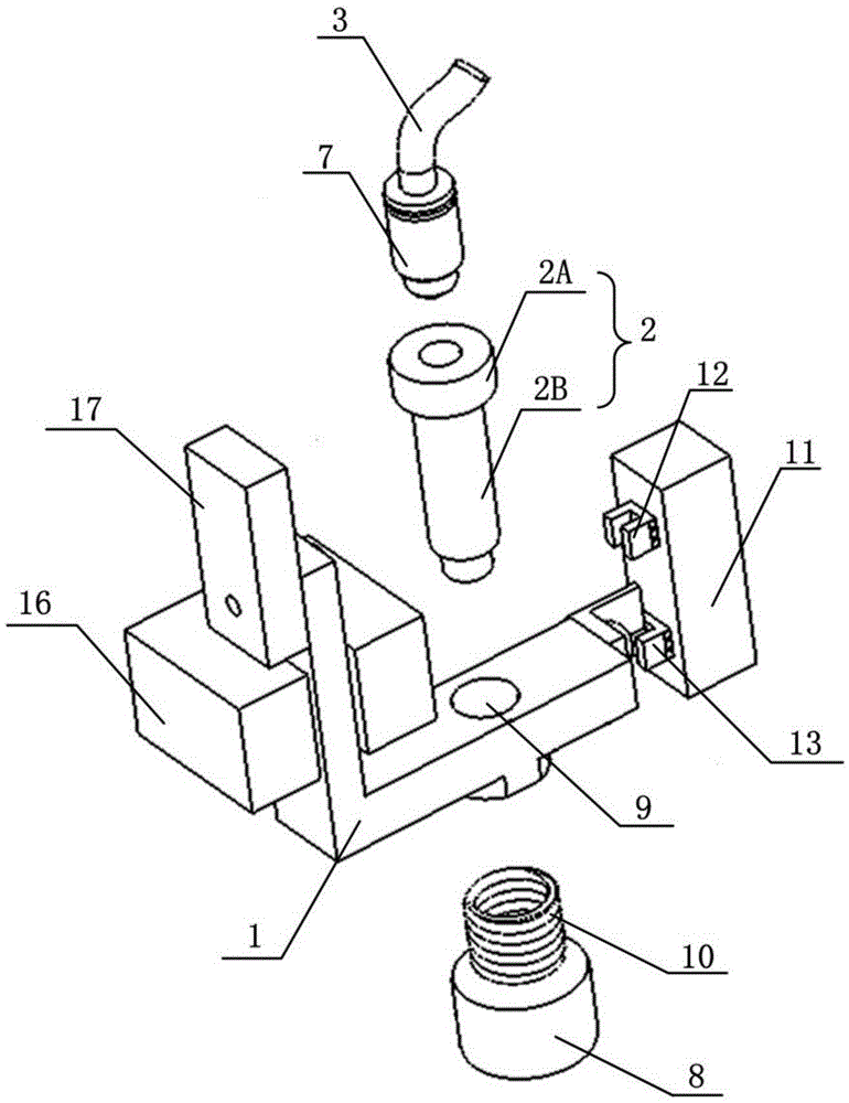

Image

  • Negative-pressure rapid butting device for sample feeding of micro-fluidic chip
  • Negative-pressure rapid butting device for sample feeding of micro-fluidic chip
  • Negative-pressure rapid butting device for sample feeding of micro-fluidic chip

Examples


Embodiment 1

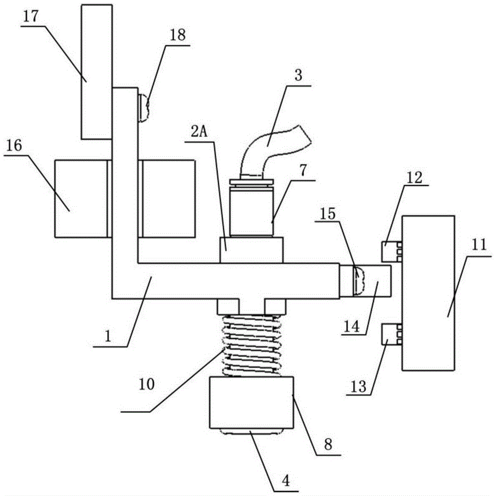
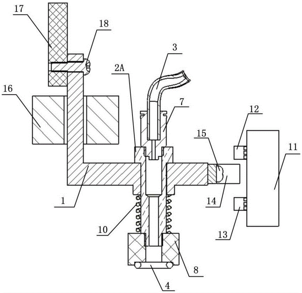
[0042] Such as Figure 1 to Figure 3 As shown, the negative pressure fast docking device for microfluidic chip injection according to the present invention includes: a driving part 1, which can reciprocate in the vertical direction; The pipeline 3 that enters the negative pressure, and the lower end is connected with the elastic sealing member 4; the follower 2 is connected to the active member 1, and driven by it, it moves downward to squeeze the microfluidic chip 5 to be docked under negative pressure. After the negative pressure is connected, it is withdrawn, wherein both the follower 2 and the sealing member 4 are of hollow structure; the hollow structure of the sealing member 4 is aligned with the air hole 6 when squeezed.

[0043]The negative pressure rapid docking device for microfluidic chip injection provided by the present invention, through the active part 1 capable of reciprocating vertically and the driven part 2 connected thereto, the driven part 2 and the sealin...

Embodiment 2

[0053] On the basis of Example 1, this example provides a method for rapid negative pressure insertion and withdrawal of samples into the microfluidic chip 5 using the negative pressure rapid docking device of Example 1.

[0054] Negative pressure docking fast access, before negative pressure docking, such as Figure 4a to Figure 4b As shown, the active part 1 is located at the position of the reset position switch 12, the microfluidic chip 5 to be docked under negative pressure is ready, the driving part 17 drives the active part 1, and drives the gas circuit joint 7 and the driven part 2 through the elastic part 10 , the interface piece 8 , the sealing piece 4 and the position switch triggering device 14 move toward the microfluidic chip 5 in the vertical direction. Movement to a certain moment, the sealing member 4 and the air hole 6 of the microfluidic chip 5 begin to contact, due to the obstruction of the microfluidic chip 5, the follower 2, the gas path joint 7, the inte...


PUM


Abstract

The invention discloses a negative-pressure rapid butting device for sample feeding of a micro-fluidic chip. The device comprises a driving element and a driven element. The driving element is capable of reciprocating in the vertical direction. The upper end of the driven element is connected with a pipe filled with negative pressure, and the lower end of the driven element is connected with an elastic sealing element. The driven element is connected to the driving element and driven by the driving element to move downwards to squeeze an air hole of the micro-fluidic chip for negative-pressure butting, and the driven element is withdrawn after negative-pressure butting is achieved. The driven element and the sealing element are each of a hollow structure, and the hollow structure of the sealing element is flush with the air hole during squeezing. The negative-pressure rapid butting device has the advantages of a high sealing property while achieving rapid butting and withdrawal of negative-pressure butting of the micro-fluidic chip..

Description

technical field [0001] The invention relates to the field of negative pressure fast docking devices, and more specifically, the invention relates to a negative pressure fast docking device for microfluidic chip injection. Background technique [0002] Microfluidic chip technology can realize microliter or even picoliter fluid control, and can integrate various processes such as sample injection, transportation, mixing, temperature control and detection, thus greatly improving detection efficiency and accuracy, and reducing Minimizing the consumption of samples and reagents, and eliminating the interference of human factors, has become a very popular detection method in the field of biomedical chemistry. Microfluidic chips are usually disposable detection chips that can be discarded after use, so they are also called disposable chips. [0003] The detection instrument of the disposable microfluidic chip consists of two parts, one is a disposable microfluidic chip, which is i...

Claims


Application Information

Patent Timeline
Patent Type & Authority Applications(China)
IPC IPC(8): G01N35/10
CPCG01N35/1095
Inventor 周武平黎海文蒋克明张涛刘聪
Owner SUZHOU INST OF BIOMEDICAL ENG & TECH CHINESE ACADEMY OF SCI
Learn More