concrete bolt

A concrete and bolt technology, applied in the direction of screws, threaded fasteners, connecting components, etc., can solve problems such as failure, and achieve the effect of reducing brittle fracture tendency, reducing brittle fracture tendency, and avoiding stress peaks

Active Publication Date: 2017-05-24
FISCHERWERKE ARTUR FISCHER GMBH & CO KG
View PDF8 Cites 0 Cited by
  • Summary
  • Abstract
  • Description
  • Claims
  • Application Information

AI Technical Summary

Problems solved by technology

Especially in the case of oblique tension, as specified in the corresponding permissible tests for concrete bolts according to ETAG, this can lead to failure

Method used


Image

  • concrete bolt
  • concrete bolt

Examples


Embodiment Construction

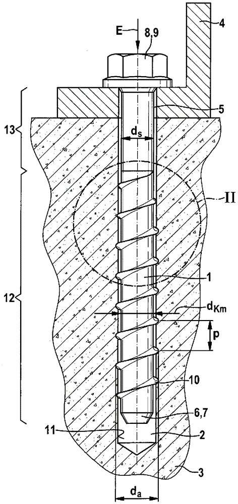
[0017] The thread-cut concrete bolt 1 according to the invention shown in the drawing is intended to be screwed into a pre-drilled hole 2 in a foundation 3 made of concrete, a wall or another mineral material. The concrete bolt 1 is screwed into the borehole 2 without dowels or other auxiliary measures, while an internal thread is automatically cut in the foundation 3 and serves to fix the object 4 in the form of a steel angle bracket. For this purpose, the concrete bolt 1 is inserted through the through-hole 5 of the body 4 before being screwed into the foundation 3 . figure 1 Shows the fully docked state. The concrete bolts 1 together with the foundation 3 form the fixture.

[0018] The concrete screw 1 has a frusto-conical constriction 6 at the front screw end 7 in the insertion direction E and has a tool engagement measure 8 at the rear screw end 9 . In the exemplary embodiment shown, the tool action measure 8 is an external hexagon, this head shape is not mandatory.

...


PUM


Abstract

The invention relates to a concrete screw (1). In order to reduce the tendency toward hydrogen-induced brittle fracture, the minor diameter dK according to the invention rises to the body diameter ds in a transition region (14) and, at the same time, the major diameter da of the thread (10) falls to the body diameter ds. In addition, according to the invention, the flank crest (15) and the flank root (16) are rounded off. As a result, the microstructure becomes more homogeneous and stress peaks are avoided.

Description

technical field [0001] The invention relates to a concrete bolt having a threaded section with a thread and a constant central core diameter over at least half its length, a threaded shank section and tool action means. Background technique [0002] Concrete bolts are understood to be bolts which can be screwed into pre-drilled holes in the concrete. Here they cut their threads automatically, so this hole must be at least partially very hard. [0003] There is a danger of hydrogen embrittlement in concrete bolts not made of stainless steel. Surface treatments such as pickling cause hydrogen to diffuse atomically into the edge layer of the concrete bolt. Especially from 1000N / mm 2 When the high strength is achieved, under the load due to the concentration of hydrogen gas, delayed brittle fracture occurs in areas with high stress. This can lead to failure, especially in the case of oblique tension, as specified in the corresponding permissible tests for concrete bolts acco...

Claims


Application Information

Patent Timeline
Patent Type & Authority Patents(China)
IPC IPC(8): F16B25/00
Inventor B.魏歇特
Owner FISCHERWERKE ARTUR FISCHER GMBH & CO KG
Why Eureka
Try Eureka