Side-pulling shaker

An oscillator and side-pull technology, which is applied in the field of side-pull oscillators, can solve the problems of poor oscillation effect, complex structure, and high cost, and achieve the effect of good oscillation effect, simple operation, and low cost

Active Publication Date: 2016-03-30
解安庆 +1
View PDF2 Cites 6 Cited by
  • Summary
  • Abstract
  • Description
  • Claims
  • Application Information

AI Technical Summary

Problems solved by technology

Some of the current oscillation operations use human hands to directly shake the test tube. This method is not only troublesome, but also the oscillation effect is not good.
In order to obtain a better vibration effect, some hospitals purchase special oscillators, but the structure is complex and the cost is high

Method used


Image

  • Side-pulling shaker
  • Side-pulling shaker

Examples


Embodiment Construction

[0018] The principles and features of the present invention are described below in conjunction with the accompanying drawings, and the examples given are only used to explain the present invention, and are not intended to limit the scope of the present invention.

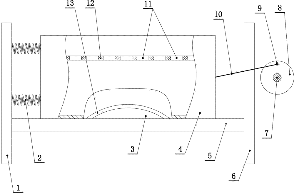
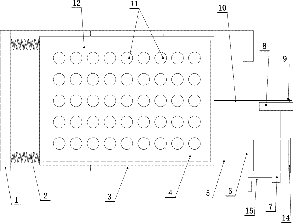
[0019] Such as figure 1 and figure 2 As shown, a side-pull oscillator includes a support plate 5, one side of the support plate 5 is fixedly connected with a vertical plate 1, and the other side is fixedly connected with a bracket 6, and the bracket 6 is "H" type, "U" type or Inverted "U" shape. The inner side of the vertical plate 1 is fixedly connected with a tension spring 2 arranged horizontally, and the other end of the tension spring 2 is fixedly connected with a test tube holding box 4. The test tube holding box 4 slides left and right and rests on the support plate 5. The test tube holding box 4 is hollow and has There is an upward opening, and the test tube holding box 4 is fixedly connected with a shelf...


PUM


Abstract

The invention provides a side-pulling shaker. The side-pulling shaker comprises a support plate, one side of the support plate is fixedly connected with a vertical plate, the other side is fixedly connected with a support, the inner side of the vertical plate is fixedly connected with transversely-arranged tension springs, the other ends of the tension springs are fixedly connected with a test tube containing box, the test tube containing box is put on the support plate in a leftwards and rightwards sliding manner, is hollow and is provided with an upward opening, the inner part of the test tube containing box is fixedly connected with a shelf, and the shelf is vertically and horizontally provided with a plurality of test tube passing holes in rows; the outer side of the support is fixedly connected with a support frame, a rotating shaft is connected onto the support frame in a relatively rotating manner, one end of the rotating shaft is in transmission connection with a rocking bar, the other end is in transmission connection with a rotary table, a tether line pin is connected onto the rotary table in a relatively rotating manner, a flexible rope is connected onto the tether line pin, the other end of the flexible rope is fixedly connected with the test tube containing box, and the flexible rope and the tension springs are respectively located at opposite sides of the test tube containing box. A protruding strip is fixedly connected onto the upper surface of the support plate, and the lower surface of the bottom wall of the test tube containing box is concave upwards to form an arc groove corresponding to the protruding strip.

Description

technical field [0001] The invention relates to a medical device, in particular to a side-pull oscillator. Background technique [0002] In medical practice, vibration operation is required in many cases, for example, inspectors oscillate samples, nurses oscillate after mixing solid medicine and liquid medicine, etc. Some of the current oscillating operations adopt the direct shaking of the test tube by hand, which is not only troublesome, but also has a bad oscillation effect. In order to obtain a better oscillation effect, some hospitals purchase special oscillators, but the structures are complex and the cost is high. Contents of the invention [0003] The invention aims at the deficiencies and provides a side-pull oscillator with simple structure, low price and good use effect. [0004] The technical scheme that the present invention solves the problems of the technologies described above is as follows: [0005] A side-pull oscillator, comprising a support plate, on...

Claims


Application Information

Patent Timeline
IPC IPC(8): B01F11/00
CPCB01F31/20B01F31/22B01F31/24B01F31/50B01F31/70B01F2101/2202
Inventor 梁艳
Owner 解安庆
Why Eureka
Try Eureka