
Sand making machine

A technology of sand making machine and crushing chamber, which is applied in the direction of grain processing, etc., which can solve the problems of not being able to meet the discharge requirements of different sand making speeds, and achieve the effects of low cost, small kinetic energy, and cost reduction

Active Publication Date: 2016-03-30
ZHENGZHOU ZHENGSHENG HEAVY IND TECH CO LTD
View PDF9 Cites 4 Cited by
  • Summary
  • Abstract
  • Description
  • Claims
  • Application Information

AI Technical Summary

Problems solved by technology

[0004] The invention provides a sand making machine to solve the technical problem existing in the prior art that the size of the outlet connected to the crushing chamber of the sand making machine is fixed and cannot meet the discharge requirements of different sand making speeds

Method used


Image

  • Sand making machine
  • Sand making machine
  • Sand making machine

Examples


Embodiment Construction

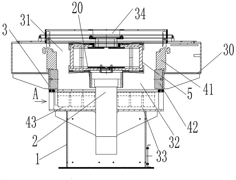
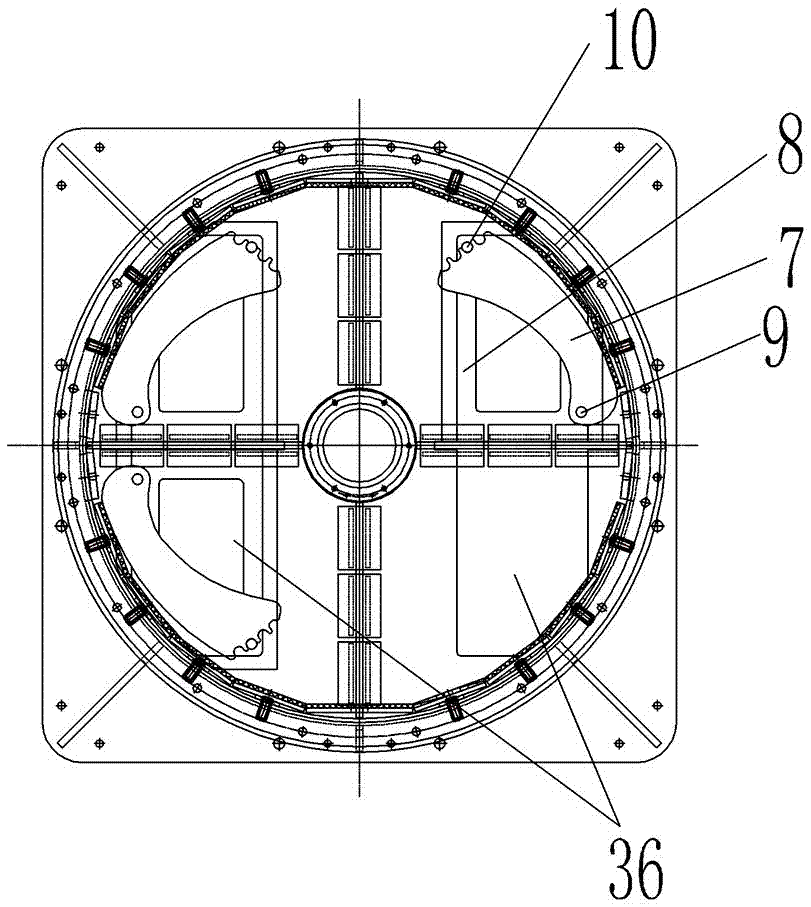
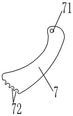
[0028] Such as Figure 1 to Figure 5 As shown, an embodiment of a sand making machine with a discharge port adjustment device, the sand making machine in this embodiment includes a chassis 1, and a crushing chamber assembly 3 is arranged on the chassis 1, and the crushing chamber assembly 3 A spindle assembly 2 extending vertically is arranged in the middle, and a rotor 5 is arranged on the top of the spindle assembly 2 .

[0029] The crushing chamber assembly 3 includes a housing 30 with a crushing chamber. The upper part of the housing 30 is provided with a feed port 34 communicating with the crushing chamber. The upper part of the crushing chamber is a primary crushing area 31 corresponding to the rotor. The circumferential direction of the housing 30 is A primary anti-friction lining 41 arranged around the rotor 5 is provided on the side wall. The lower part of the crushing chamber is a blanking area 33, and the bottom plate 3 of the housing 30 is provided with a discharg...


PUM


Abstract

The invention relates to a sand making machine which comprises a crushing cavity assembly, wherein the crushing cavity assembly comprises a housing provided with a crushing cavity; a discharge port communicated with the crushing cavity is formed in the housing; a blocking adjusting plate for adjusting the size of the discharge port is movably assembled at the discharge port in the housing; and a locking structure for locking the blocking adjusting plate after the blocking adjusting plate is adjusted in place is arranged between the blocking adjusting plate and the housing. According to the sand making machine, the blocking adjusting plate is movably assembled at the discharge port in the housing, the size of the discharge port is adjusted through adjusting the position of the blocking adjusting plate during use, and after the adjustment is finished, the blocking adjusting plate is locked by the locking structure. In this way, the size of the discharge port can be adjusted according to the practical discharge requirements, so as to meet the discharge requirements on different sand making speeds.

Description

technical field [0001] The invention relates to a sand making machine. Background technique [0002] Sand making machines are widely used in many fields such as metallurgy, building materials, roads, railways, water conservancy and chemical industries, and are suitable for crushing and shaping of soft or medium hard and extremely hard materials. The working principle of the rotor centrifugal sand making machine is that the material enters the high-speed rotating rotor and is thrown out of the fixed liner under the action of centrifugal force. The material is directly crushed or rebounds and collides with other materials again, so as to achieve the purpose of crushing and making sand. . [0003] A Chinese utility model patent with the authorized announcement number CN202410787U discloses a sand making machine, which includes a body with a feeding hopper, and a high-speed rotating rotor inside the body, and the feeding port sends materials into the rotor. , and rotates with ...

Claims


Application Information

Patent Timeline
IPC IPC(8): B02C19/00B02C23/00
CPCB02C19/0018B02C23/00
Inventor 吴传戈于晓东张忠义刘峰张昭
Owner ZHENGZHOU ZHENGSHENG HEAVY IND TECH CO LTD
Learn More