
Welding method for focusing ring assembly

A welding method and focus ring technology, applied in welding equipment, electron beam welding equipment, metal processing equipment, etc., can solve the problems of poor welding quality and complicated welding process of focus ring components, so as to improve welding efficiency, simplify welding process, The effect of increasing the success rate

Inactive Publication Date: 2016-03-30
KONFOONG MATERIALS INTERNATIONAL CO LTD
View PDF10 Cites 4 Cited by
  • Summary
  • Abstract
  • Description
  • Claims
  • Application Information

AI Technical Summary

Problems solved by technology

[0006] However, in the existing method, in the process of welding the focus ring and the fixed assembly, there is a

Method used


Image

  • Welding method for focusing ring assembly
  • Welding method for focusing ring assembly

Examples


Embodiment Construction

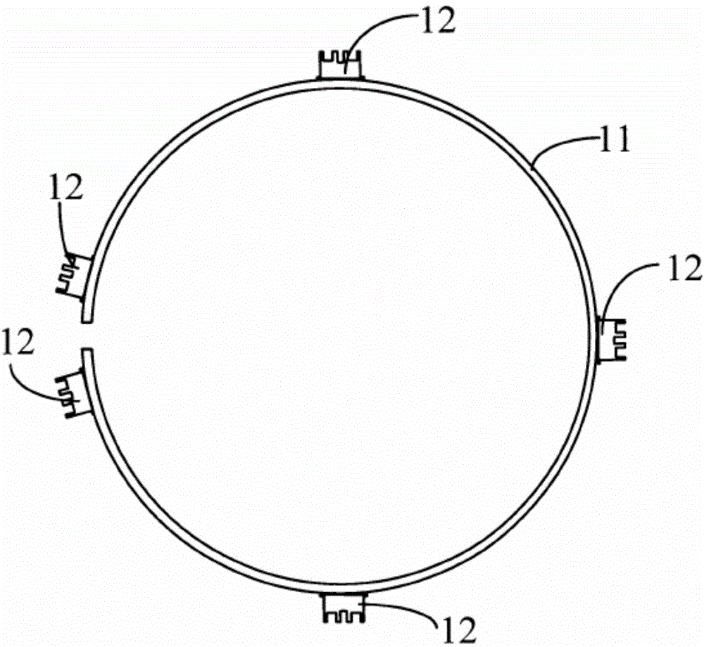
[0027] As described in the background, in the existing method, there is a problem that the welding process is complicated during the process of welding the focus ring and the fixed assembly, and the welding quality of the existing focus ring assembly is poor.

[0028] It turns out that the existing method usually chooses vacuum electron beam welding to weld the fixed component and the focus ring together. However, in the existing method, when welding the fixing component and the focus ring, one fixing component is usually welded to the focus ring, and a vacuuming process is required during this process. After one welding, it is necessary to open the vacuum chamber, then rotate the focus ring, and make another fixed component align with the welding port, and then weld this fixed component. This process continues until all mounting components are welded together with the focus ring. This welding method is very inefficient, and repeating the same complicated welding process also...


PUM


Abstract

A welding method for a focusing ring assembly includes the steps that at least two fixing assemblies to be welded are primarily fixed to the outer side face of a focusing ring; the focusing ring with the fixing assemblies being primarily fixed is arranged in a welding chamber; the welding chamber is vacuumized; and after vacuumizing, the fixing assemblies which are primarily fixed are subjected to vacuum electron beam welding one by one. By means of the welding method for the focusing ring assembly, welding efficiency of products is improved.

Description

technical field [0001] The invention relates to the field of semiconductor manufacturing, in particular to a welding method for a focus ring assembly. Background technique [0002] Sputtering is a physical vapor deposition (PVD) coating method. It bombards the target with charged particles, causing the surface atoms of the target to collide and transfer energy and momentum. The target atoms escape from the surface and deposit process on the substrate. Metal, alloy or dielectric films can be formed on the substrate surface by sputtering process. [0003] Since the direction of the charged particles bombarding the target is uncertain, the directionality of the target atoms escaping from the target surface is poor, that is, the target atoms will leave the target surface from various angles, and then reach the substrate surface along a straight line , which in turn makes the target atoms have poor coverage of the bottom and sidewalls of the contact holes or vias on the substra...

Claims


Application Information

Patent Timeline
IPC IPC(8): B23K15/06
Inventor 姚力军潘杰相原俊夫大岩一彦王学泽张冬青
Owner KONFOONG MATERIALS INTERNATIONAL CO LTD
Learn More