Glass pipeline and magnetic selector connecting system for flour processing

A connection system and magnetic separator technology, applied in the direction of pipeline connection layout, pipe/pipe joint/pipe fitting, mechanical equipment, etc., can solve the problems of inconvenient raw material transportation and observation, poor wear resistance, etc., to increase wear resistance and reduce system cost, damage prevention effect

Inactive Publication Date: 2016-03-30
湖北丰庆源粮油集团有限公司
0 Cites 0 Cited by

AI-Extracted Technical Summary

Problems solved by technology

[0004] In order to overcome the deficiencies in the prior art, the purpose of the present invention is to provide a connection system between a glass pipeline for flour pr...

Method used

As shown in Fig. 1, Fig. 2, Fig. 3, Fig. 4, the present invention is positioned at the angle iron 1 on the edge, is positioned at the square iron frame 3 of end and glass 2 forms glass pipe, and the angle iron 1 that adopts is convenient The purchased standard parts, four angle irons 1 siege quadrilateral, use four pieces of glass 2 to bond to the angle iron 1 to form the glass pipe wall, and the inner side of the square iron frame 3 at the end is welded on the angle iron 1, on the one hand Used to prevent the glass 2 from slipping out of the top, on the other hand, used as a connecting flange for multiple pipes. The bottom outlet of glass pipe is connected with magnetic separator 5, and for convenience glass pipe is connected with magnetic separator 5, the circular flange plate-4 of the bottom of glass pipe is designed into the shape of outer circl...

Abstract

The invention discloses a glass pipeline and magnetic selector connecting system for flour processing and relates to the field of flour processing. Angle iron at the arrises, square iron frames at the ends and glass form a glass pipeline; the glass pipeline is in screwed connection with a magnetic selector through a first round flange plate on the glass pipeline and a second round flange plate on the magnetic selector; the glass is glued to the four angle iron through glass glue; two sets of glass pipelines are fixedly connected through screws by means of the square iron frames; a magnetic separation core of the magnetic selector is connected to a shell through connecting rods. The glass pipeline and magnetic selector connecting system for flour processing is good in visibility, and an operator can visually observe conditions of substances in the pipelines, so that smooth operation of a technological process is guaranteed; the system cost is reduced; by means of glass pipeline and magnetic selector connection, metal in flour is advantageously screened out through the magnetic selector, and the metal is prevented from damaging equipment during processing.

Application Domain

Pipe connection arrangements

Technology Topic

EngineeringVisibility +4

Image

  • Glass pipeline and magnetic selector connecting system for flour processing
  • Glass pipeline and magnetic selector connecting system for flour processing
  • Glass pipeline and magnetic selector connecting system for flour processing

Examples

  • Experimental program(1)

Example Embodiment

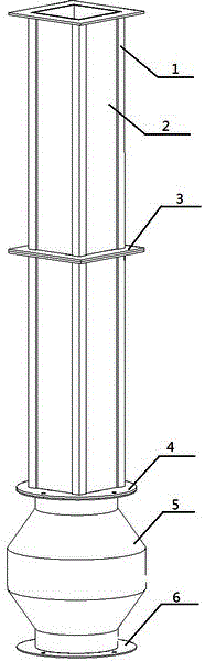
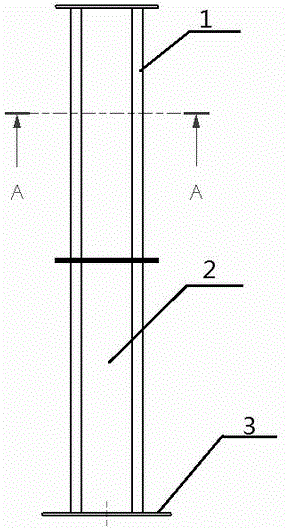
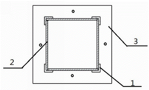
[0017] Such as figure 1 , figure 2 , image 3 , Figure 4 As shown, the angle iron 1, the square iron frame 3 at the end, and the glass 2 of the present invention form a glass pipe. The angle iron 1 used is a standard part that is easy to buy. The four angle irons 1 are surrounded by a quadrilateral. Four pieces of glass 2 are bonded to the angle iron 1 to form the wall of the glass pipe. The inner side of the square iron frame 3 at the end is welded to the angle iron 1. On the one hand, it is used to prevent the glass 2 from sliding out of the top, and on the other hand, it is used For connecting flanges for multiple pipelines. The discharge port at the bottom of the glass pipe is connected with the magnetic separator 5. In order to facilitate the connection between the glass pipe and the magnetic separator 5, the circular flange 4 at the bottom of the glass pipe is designed to have an outer circle and an inner square shape. The glass has strong wear resistance and visibility. The pipe uses the angle iron 1 as the skeleton, which is firm and reliable, and is convenient to connect with the magnetic separator 5 and the outlet of other equipment.
[0018] Since large pieces of glass are easier to break, in order to reduce the risk of glass breakage, the pipeline is generally shorter. When long-distance transportation is required, such as figure 2 Multi-section connection shown to increase safety and reliability.
[0019] It should be noted that although the embodiment and the drawings of the specification only show the quadrilateral pipe structure composed of angle iron, the main idea of ​​the present invention is to replace the iron pipe with glass to enhance the wear resistance and visibility. The reason for using angle iron is only for cost and material selection considerations. The present invention not only covers the above-mentioned quadrilateral pipe structure, but can also be other structures, such as a triangular structure composed of a 60-degree angle iron with excellent stability, or other polygonal structures such as pentagons.
[0020] The magnetic separator 5 includes a housing, a circular flange plate 6 and a magnetic separation core 8, and the magnetic separation core 8 is connected to the housing by a connecting rod 7. When the material contains metal that can be absorbed by the magnet, the magnetic separator 5 can filter out the metal to prevent the metal from damaging the equipment in the processing process.

PUM

no PUM

Description & Claims & Application Information

We can also present the details of the Description, Claims and Application information to help users get a comprehensive understanding of the technical details of the patent, such as background art, summary of invention, brief description of drawings, description of embodiments, and other original content. On the other hand, users can also determine the specific scope of protection of the technology through the list of claims; as well as understand the changes in the life cycle of the technology with the presentation of the patent timeline. Login to view more.

Similar technology patents

Contrast enhancement RDH method and system based on histogram movement

PendingCN113781285Agood visibilityIncrease embedding capacity
Owner:SHANDONG NORMAL UNIV

Settlement observation point device for reinforced concrete framed bent structure

PendingCN112857311Agood visibilityEasy to observe
Owner:MCC CAPITAL ENGINEERING & RESEARCH +1

Vehicle and light emitting body control device

PendingCN114763092AGood visibility
Owner:HONDA MOTOR CO LTD

Classification and recommendation of technical efficacy words

  • good visibility
  • Improve wear resistance

Vehicular lamp

ActiveUS20150277027A1large surface areagood visibility
Owner:KOITO MFG CO LTD

Medical x-ray ct imaging apparatus

ActiveUS20110044520A1good visibility
Owner:MORITA MFG CO LTD

Low-backlight image visibility enhancement method and system

InactiveUS20090184915A1electric power consumption be savegood visibility
Owner:NAT TAIWAN UNIV

Contact lens and method of manufacturing the same

InactiveUS20090059166A1good visibilityreduce scatter
Owner:MENICON CO LTD

Device for monitoring the exterior of a motor vehicle

InactiveUS20060250500A1good visibilitylow cost
Owner:DAIMLER AG

Belt with Wear-Resistant Anti-Static Fabric

ActiveUS20100197435A1improve wear resistanceadvantageous frictional property
Owner:THE GATES CORP

High wear-resistant and cold-resistant toughened nylon composite material

ActiveCN102051043AImprove wear resistanceGood mechanical properties and low temperature resistance
Owner:SHANGHAI KINGFA SCI & TECH +1
Why Eureka
Try Eureka