An Experimental Device for Measuring Venturi Overflow

An experimental device, Venturi technology, is applied in measuring devices, testing/calibrating devices, detecting fluid flow by measuring differential pressure, etc. It can solve the problems of weakening vapor diffusion flow and decreasing condensation efficiency, and achieves novel design, easy operation, The effect of simple and compact structure

Active Publication Date: 2018-11-06
GUILIN UNIV OF AEROSPACE TECH
View PDF5 Cites 0 Cited by
  • Summary
  • Abstract
  • Description
  • Claims
  • Application Information

AI Technical Summary

Problems solved by technology

It can be seen from this that when the non-condensable gas discharge aperture and orientation are not set properly, the overflow of non-condensable gas will weaken the diffusion flow of steam and reduce the condensation efficiency

Method used


Image

  • An Experimental Device for Measuring Venturi Overflow

Examples


Embodiment Construction

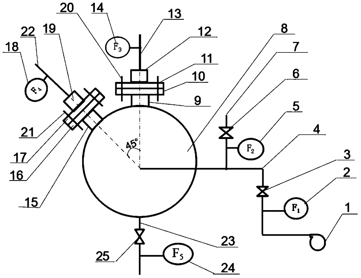
[0021] The present invention is described in further detail below in conjunction with accompanying drawing:

[0022] see figure 1 , the experimental device for measuring Venturi overflow of the present invention includes a main air pipe 8 and an air inlet pipe 4, a fan 1 is connected to the air inlet pipe 4, and a first flow meter 2, an air inlet valve 3 and a discharge pipe 4 are installed on the air inlet pipe 4. Trachea 7, second flow meter 5 and deflation valve 6 are installed on deflation pipe 7. The other end of the air intake pipe 4 is connected to one end of the main air pipe 8, and a Venturi bottom pipe I 9 is welded at the top center of the middle section of the main air pipe 8, on which the lower orifice plate I 10 and the upper orifice plate I 11 are respectively welded , Venturi top pipe I 12 is provided on the upper orifice plate I 11, and the lower orifice plate I 10 and the upper orifice plate I 11 are connected together with the bolt group I 20. Venturi bott...


PUM


Abstract

The invention relates to an experimental device for measuring the Venturi transpiration amount, and belongs to the field of fluid machines. The experimental device comprises a main air tube and an air inlet tube connected with the main air tube. The inlet end of the air inlet tube is provided with a fan. A first flow meter, an air inlet valve and an air exhaust tube are sequentially arranged on a tubeline connecting with the air inlet tube with the main air tube. The air exhaust tube is provided with a second flow meter and an air exhaust valve. A plurality of Venturi tubes are perpendicularly arranged on the tube wall of the main air tube. Each Venturi tube is provided with a transpiration tube. Each Venturi tube is composed of a Venturi top tube and a Venturi bottom tube, wherein a porous partition plate with the pore diameter smaller than that of the corresponding Venturi tube is arranged between the Venturi top tube and the Venturi bottom tube. The device is simple and compact in structure, novel in design, easy to operate, safe and reliable.

Description

technical field [0001] The invention belongs to the field of fluid machinery and relates to an experimental device for measuring venturi overflow. Background technique [0002] The condenser is one of the main heat exchange equipment in the industrial sector, and the non-condensable gas contained in the condenser is one of the important reasons for the decrease of the condensation efficiency. Therefore, the exclusion of non-condensable gas is an important key to ensure the design capability. At present, the non-condensable gas discharge port is usually located at the place where the non-condensable gas is easy to accumulate. If the aperture is too large, a large amount of working fluid will be lost. If the aperture is too small, the non-condensable gas cannot be discharged in time, which will reduce the condensation efficiency; The direction of overflow in the air film layer may also hinder the diffusion flow of steam and reduce the condensation amount of steam. Due to the...

Claims


Application Information

Patent Timeline
Patent Type & Authority Patents(China)
IPC IPC(8): G01F25/00G01F1/44
CPCG01F1/44G01F25/00
Inventor 张俊霞
Owner GUILIN UNIV OF AEROSPACE TECH
Why Eureka
Try Eureka