Testing clamp and method for improving mechanical fatigue performance of composite material

A technology of mechanical fatigue and composite materials, which is applied in the field of sample preparation methods and supporting fixtures for enhancing the detection strength of materials. Effect

Inactive Publication Date: 2016-03-30
ZHEJIANG HENGSHI FIBER FOUND CO LTD
View PDF11 Cites 2 Cited by
  • Summary
  • Abstract
  • Description
  • Claims
  • Application Information

AI Technical Summary

Problems solved by technology

However, the fixture affects the detection accuracy and has a complicated structure

Method used


Image

  • Testing clamp and method for improving mechanical fatigue performance of composite material
  • Testing clamp and method for improving mechanical fatigue performance of composite material
  • Testing clamp and method for improving mechanical fatigue performance of composite material

Examples


Embodiment 1

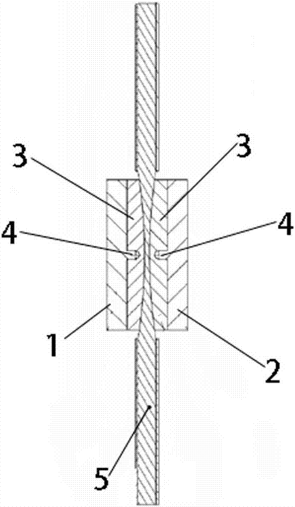
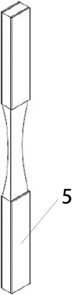
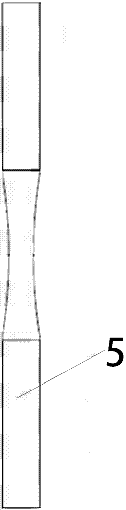
[0041] Such as figure 1 As shown, a detection fixture for improving the mechanical fatigue performance of composite materials includes a left splint 1, a right splint 2, the bottom surface of the left splint 1, and the top surface of the right splint 2 are fixedly connected with a protection pad 3 at the same time, and the protection pad 3 has a prominent arc. The protective pad 3 of the left splint 1 is fixedly connected through the positioning column 4 fixedly connected at the center of the left splint 1 . Firmly fix the protective pad 3 on the left splint 1. Similarly, the protective pad 3 of the right splint 2 is fixedly connected through the positioning column 4 fixedly connected at the center of the right splint 2, so that the protective pad 3 is firmly fixed on the right splint 2. Specifically, the bottom surface of the left splint 1 is fixedly connected with the positioning column 4, and the left splint 1 is fixedly connected with the protective pad 3 on the left spl...

Embodiment 2

[0044] Such as figure 1 As shown, a clamping tool for materials to be inspected includes a left splint 1, a right splint 2, the bottom surface of the left splint 1, and the top surface of the right splint 2 are fixedly bonded with a protective pad 3 at the same time, and the protective pad 3 has Prominent camber. The protective pad 3 of the left splint 1 is fixedly connected through the positioning column 4 fixedly connected at the center of the left splint 1 . Firmly fix the protective pad 3 on the left splint 1. Similarly, the protective pad 3 of the right splint 2 is fixedly connected by the positioning column 4 fixedly connected at the center of the right splint 2, so that the protective pad 3 is firmly fixed on the right splint 2. Specifically, the bottom surface of the left splint 1 is fixedly connected with the positioning column 4, and the left splint 1 is fixedly connected with the protective pad 3 on the left splint 1 through the positioning column 4. The position...

Embodiment 3

[0047] Such as figure 1 As shown, a material fixing tool to be inspected comprises a left splint 1 and a right splint 2, the bottom surface of the left splint 1 is a protruding arc surface, and the top surface of the right splint 2 is a protruding arc surface, the left splint 1 and the The radians of the arc surfaces of the right splint 2 are identical. A protection pad 3 is bonded to the protruding arc surface of the left splint 1 , and a protection pad 3 is also bonded to the protruding arc surface of the right splint 2 . In this embodiment, the left splint 1 and the right splint 2 are quadrilateral structures.


PUM


Abstract

The invention relates to a testing clamp and a testing method for improving mechanical fatigue performance of a composite material. The clamp comprises a left clamping plate (1) and a right clamping plate (2), wherein the bottom surface of the left clamping plate and the top surface of the right clamping plate are fixedly connected with a protection pad (3) simultaneously; and the protection pad (3) has a protruding cambered surface. Through the clamp and the method for detecting the strength of a reinforced material through the clamp, the stability of test data is further ensured. A bronze drum clamp is used for clamping a spline, so that the stability of the spline is protected to the maximal extent; testing is facilitated; the application range is relatively wide; and the qualified rate of testing is relatively high. In addition, breaking points of the spline tested by using the clamp provided by the invention and the method provided by the invention are effective and consistent; and the data result is accurate and stable.

Description

technical field [0001] The invention relates to the technical field of material detection, in particular to a sample preparation method for enhancing material detection strength and a supporting fixture thereof. Background technique [0002] During the application process, the reinforced material product is constantly subjected to the influence of itself and the external climate environment and mechanical environment, but it still needs to be able to work normally, which requires tests to verify it. The conventional spline in the traditional fatigue test has the same size, so the breaking point is not in the middle position during the test, which makes the test invalid. In addition, the conventional spline is glued with a reinforcing sheet, which tends to fall off during the test. As a result, the inaccuracy of the discrete rate data cannot meet the detection requirements. [0003] The Chinese invention patent with the application number of 201410158355.3 discloses a steel ...

Claims


Application Information

Patent Timeline
Patent Type & Authority Applications(China)
IPC IPC(8): G01N3/04G01N3/00
Inventor 刘连学
Owner ZHEJIANG HENGSHI FIBER FOUND CO LTD
Why Eureka
Try Eureka