
Display panel as well as preparation method and application thereof

A technology for display panels and substrates, which can be used in instruments, nonlinear optics, optics, etc., and can solve problems such as deformation of the AA area

Inactive Publication Date: 2016-03-30
BOE TECH GRP CO LTD +1
View PDF10 Cites 5 Cited by
  • Summary
  • Abstract
  • Description
  • Claims
  • Application Information

AI Technical Summary

Problems solved by technology

By adding phase-change energy storage materials to the frame sealant of the display panel, the problem of heat absorption and release when the frame sealant is heated is solved, thereby solving the problem of obvious deformation of the AA area due to heat during IC bonding

Method used


Image

  • Display panel as well as preparation method and application thereof
  • Display panel as well as preparation method and application thereof
  • Display panel as well as preparation method and application thereof

Examples


Embodiment 1

[0039] Embodiment 1 A display panel

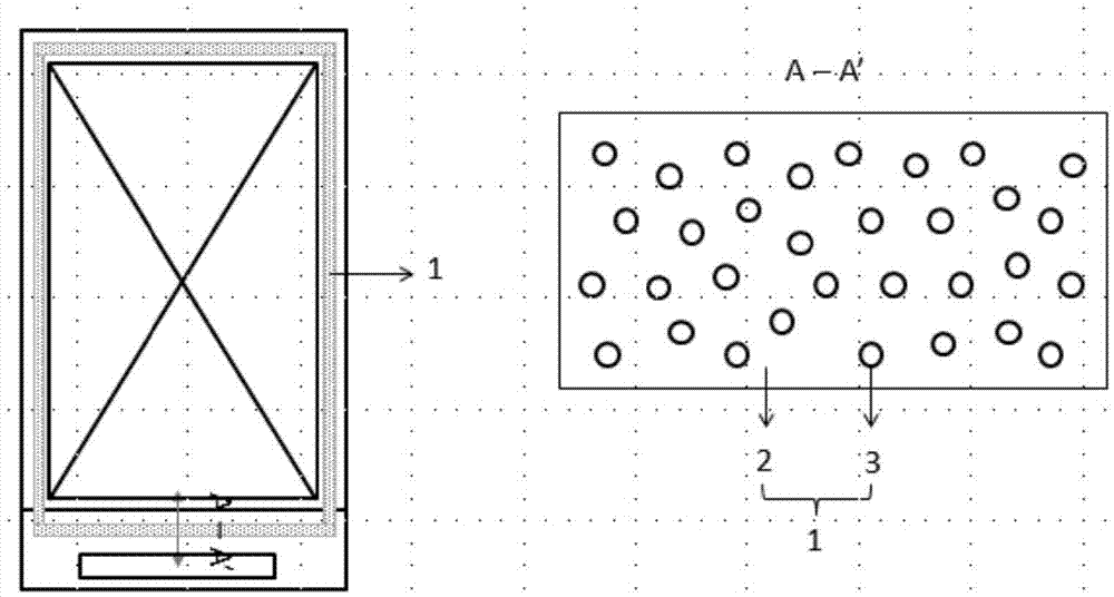
[0040] This embodiment provides a display panel, including a first substrate, a second substrate, and a sealant cured between the first substrate and the second substrate; the sealant includes a matrix material, dispersed in the matrix material thermal phase change materials. The structure of the sealant is as follows figure 1 shown.

[0041] Wherein, the thermally induced phase change material accounts for 4% of the total mass of the sealant.

[0042] Wherein, the thermally induced phase change material is selected from polyurethane block copolymers.

[0043] Wherein, the matrix material is photosensitive resin, photoinitiator, photosensitive crosslinking agent and auxiliary agent.

[0044]Since the thermal deformation temperature of glass is about 80°C, and the hot pressing temperature during IC bonding is generally above 200°C, the thermal deformation caused by heat during IC bonding cannot be ignored. The display panel obtained i...

Embodiment 2

[0045] Embodiment 2 A display panel

[0046] This embodiment provides a display panel, using the structure and materials described in Embodiment 1, the difference is:

[0047] (1) The thermally induced phase change material accounts for 0.2% of the total mass of the sealant.

[0048] (2) The thermally induced phase change material is selected from PEG / MDI / glycerol terpolymer cross-linked copolymers.

[0049] The test results show that the display panel obtained in this embodiment has basically the same effect as that in embodiment 1.

Embodiment 3

[0050] Embodiment 3 A display panel

[0051] This embodiment provides a display panel, including a first substrate, a second substrate, and a sealant cured between the first substrate and the second substrate; the sealant includes a matrix material, dispersed in the matrix material Thermally induced phase change materials, conductive gold balls.

[0052] Wherein, the thermally induced phase change material accounts for 12% of the total mass of the sealant.

[0053] Wherein, the thermally induced phase change material is selected from vanadium dioxide.

[0054] Wherein, the matrix material is photosensitive resin, photoinitiator, photosensitive crosslinking agent and auxiliary agent.

[0055] The test results show that the display panel obtained in this embodiment has basically the same effect as that in embodiment 1.


PUM


Abstract

The invention relates to a display panel. The display panel comprises a first base plate, a second base plate and a frame sealant cured between the first base plate and the second base plate, wherein the frame sealant comprises a base material and a thermally-induced phase-change material dispersed in the base material. By adding a specific material, namely the thermally-induced phase-change material, into the base material of the frame sealant, the frame sealant can absorb heat to have phase change; the heat of an IC end is stored into the phase-change material so that the effect of blocking the heat of the IC end from being transmitted to an AA region is realized. Therefore, AA region deformation caused by the heat in an IC bonding process is reduced, and the effect of improving COGmura is realized.

Description

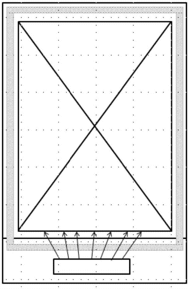
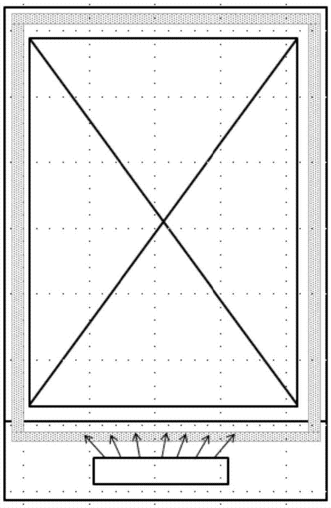
technical field [0001] The invention relates to a display panel and its preparation method and application, belonging to the technical field of liquid crystal display. Background technique [0002] In recent years, with the popularization of various electronic display devices, TVs, cars, smart watches, etc. have higher requirements for thinner and lighter screens and display quality, and thinner and lighter screens will cause IC bonding, such as figure 2 As shown, due to the difference in the thermal expansion size of the glass and the IC, a large amount of heat is transferred to the AA area, causing deformation of the Glass near the IC area, which changes the distance between the upper and lower glass of the liquid crystal cell in the display area, resulting in the displayed color. There is also a difference, this bad is called COGmura. COGMura is a common defect of the display, especially when the deformed area is close to the AA area, the COGmura phenomenon is more serio...

Claims


Application Information

Patent Timeline
IPC IPC(8): G02F1/1339
CPCG02F1/1339G02F1/13398
Inventor 徐元杰臧鹏程刘庭良高山王杨
Owner BOE TECH GRP CO LTD
Learn More