

Touch display apparatus
A touch display device and touch area technology, applied in the direction of instrument, electrical digital data processing, input/output process of data processing, etc., can solve the problems of high thickness of ink layer, air bubbles, etc. The effect of reducing the probability of level difference and air bubbles
- Summary
- Abstract
- Description
- Claims
- Application Information
AI Technical Summary
Problems solved by technology
Method used
Image

Examples
Embodiment Construction
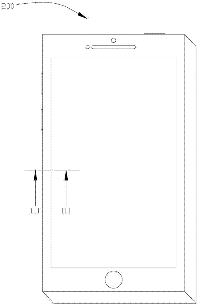
[0014] see figure 1 , the touch display device 200 provided in the first embodiment of the present invention defines a touch area 200a and a non-touch area 200b. Wherein, the touch area 200a is used for displaying images and receiving touch operations. The non-touch area 200b is arranged around the touch area 200a.
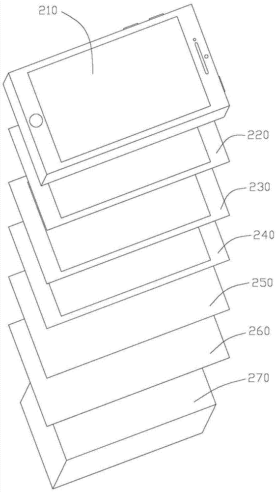
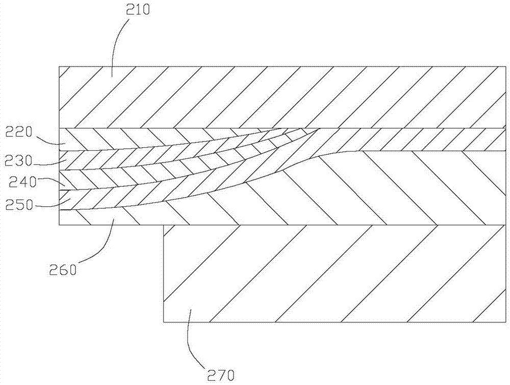
[0015] In this embodiment, the touch display device 200 is an add-on touch display device. Specifically, please also refer to figure 2 and image 3 , the touch display device 200 includes a cover plate 210 , a decoration layer 220 , a spacer layer 230 , a shielding layer 240 , a touch layer 250 , a colloid layer 260 and a display panel 270 . Wherein, the cover plate 210 is located on the outermost side of the touch display device 200 , and is used to protect the components inside the touch display device 200 . In this embodiment, the material of the cover plate 210 is tempered glass. In other embodiments, the cover 210 may also be a film-type cover, such as...
PUM
| Property | Measurement | Unit |
|---|---|---|
| Thickness | aaaaa | aaaaa |
| Thickness | aaaaa | aaaaa |
Abstract
Description
Claims
Application Information