Direct-current traction trolley for motor car

A DC traction and EMU technology, applied to switchgear, pull-out switch cabinets, electrical components, etc., can solve problems such as troublesome push and pull, unreliable interlocking, etc., to eliminate potential safety hazards, to ensure reliable connection of circuit breakers, and to avoid misuse The effect of the operation

Active Publication Date: 2016-03-30
XINGJI ELECTRIC APPLIANCE CO LTD
View PDF7 Cites 1 Cited by
  • Summary
  • Abstract
  • Description
  • Claims
  • Application Information

AI Technical Summary

Problems solved by technology

[0004] In order to solve the problems in the background technology that the existing DC circuit breaker for motor vehicles is troublesome to advance and exit, and the interlock is unreliable, the present invention provides a DC traction trolley for motor vehicles

Method used


Image

  • Direct-current traction trolley for motor car
  • Direct-current traction trolley for motor car
  • Direct-current traction trolley for motor car

Examples


Embodiment 1

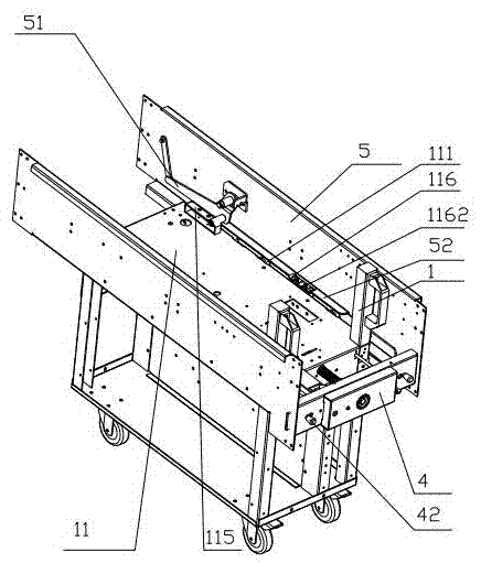
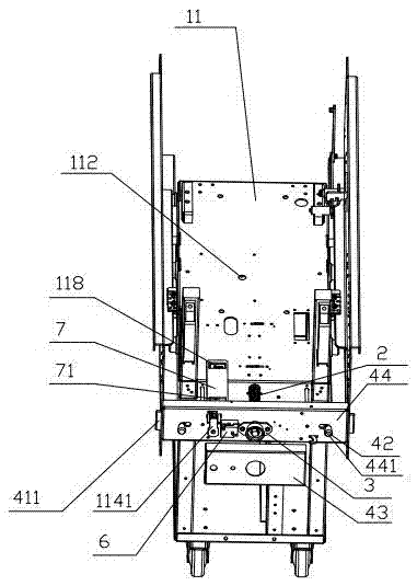
[0038] Embodiment one: see attached figure 1 , 2 , 5-18, the handle 42 includes a driving part 421 inserted into the slide plate 41, a connecting part 422 passing through the positioning frame 44, and a handle part 423 that is convenient to hold, and the connecting part 422 is linked with the handle part 423 , the connecting portion 422 is sheathed outside the driving portion 421 and slidably fits with the driving portion 421 , and the connecting portion 422 is provided with a step 4221 that engages with the positioning frame 44 . With such a structure, when the handle part drives the sliding plate to slide through the driving part, the connecting part pops up under the action of the spring (not shown in the drawing), so that the step is locked with the positioning frame, so that the handle and the end beam are reliably locked together. Avoid skateboarding. Specifically, the positioning frame 44 is provided with a limit locking hole 441 , and the limit locking hole 441 has a...

Embodiment 2

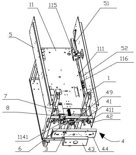
[0039] Embodiment two: see attached Figure 3-18 , the end beam 4 is provided with an interlocking plate 48, and the interlocking plate 48 is provided with a plurality of notch slots 481 (a plurality refers to at least two, and includes two notch slots), the described The handle 42 engages with different notches 481 on the interlocking plate 48 so that the sliding plate 41 is in the first position or the second position. In the present invention, the reliable positioning of the slide plate is realized through the engagement between the handle and the notch on the interlocking plate. When the handle is inserted into one notch, the vehicle frame can be pushed in or withdrawn from the cabinet, and when the handle is inserted into another notch After the handle drives the slide plate to move during the groove, the slide plate makes the screw mandrel rotate to a limited position. The interlocking plate 48 is provided with a limit baffle 482, so that when the interlocking plate mov...


PUM


Abstract

The invention discloses a direct-current traction trolley for a motor car, and aims at solving the problem that an existing direct-current breaker for the motor car is inconvenient to push forwards and backwards, and unreliable in interlock. The direct-current traction trolley comprises a frame, a screw rod, a handle rack, an end beam, a hand shank and a trolley body, wherein driving wheels are arranged at two sides of the trolley body; a sliding plate and a handle are arranged on the end beam; one end of the screw rod is arranged on the end beam and the other end passes through the sliding plate and the end beam and is arranged on the trolley body; the sliding plate comprises a first position and a second position; the first position is clamped with the end beam through the handle to limit rotation of the screw rod; the second position is clamped with side plates to relieve rotation limit on the screw rod after being driven to slip oppositely to the end beam by the handle; and the sliding plate has a movement trend close to the second position. According to the direct-current traction trolley for the motor car, the end beam is fixed reliably, and meanwhile, the rotation of the screw rod is limited through the sliding plate, so that misoperation of a worker is avoided; the safety of the worker is ensured; and the direct-current traction trolley has the advantages of being convenient to assemble, reliable to interlock, stable in action, reliable in connection of the breaker, long in service lifetime and the like.

Description

technical field [0001] The invention relates to a circuit breaker traction trolley, in particular to a DC traction trolley for motor vehicles. Background technique [0002] Due to the unique advantages of the DC power supply system, people pay more and more attention to the research of the DC power supply system, and the connection between the DC power supply system and daily life is getting closer and closer. At present, many important industries such as urban trolleybus, subway, smelting, chemical industry, solar power generation, rolling material, ship power, mining and so on have adopted DC power supply system. [0003] The DC circuit breaker is the guarantee for the safe operation of the DC power supply system. It has the protection function of cutting off the fault current of the circuit and is the most important protection component in the DC system. As people's requirements for the reliability of the power supply system become more and more stringent, and the DC pow...

Claims


Application Information

Patent Timeline
Patent Type & Authority Applications(China)
IPC IPC(8): H02B11/133H02B1/052
CPCH02B1/052H02B11/133
Inventor 王瑞元陈淼泽胡金昌
Owner XINGJI ELECTRIC APPLIANCE CO LTD
Why Eureka
Try Eureka