Method, device and system for coding and decoding signal

A coding and decoding method and technology of electrical signals, which are applied in the field of devices and systems, and signal coding and decoding methods, can solve the problems of low signal recognition rate, low optical signal recognition rate, and reduction, and achieve the effect of high communication efficiency

Active Publication Date: 2016-03-30
KUANG CHI INTELLIGENT PHOTONIC TECH
View PDF7 Cites 10 Cited by
  • Summary
  • Abstract
  • Description
  • Claims
  • Application Information

AI Technical Summary

Problems solved by technology

[0004] But on the one hand, the bright and dark duration of the light signal emitted by the LED light of the portable electronic device will change randomly, making the recognition rate of the light signal low; on the other hand, the stroboscopic characteristics of the LED light of different electronic devices are different. , and the receiving parameters set at the receiving end of the light have been relaxed to a large extent in order to adapt to the sending end, which makes some portable electronic devices with better stroboscopic characteristics reduce their performance in order to adapt to this receiving parameter, even so , there are still portable electronic devices that do not match this parameter, and their signal recognition rate is still low; in addition, when the parameters of the light signal sent by the LED light change, the receiving end needs to be upgraded, which makes system upgrade maintenance difficult. very complicated

Method used


Image

  • Method, device and system for coding and decoding signal
  • Method, device and system for coding and decoding signal
  • Method, device and system for coding and decoding signal

Examples


no. 1 example

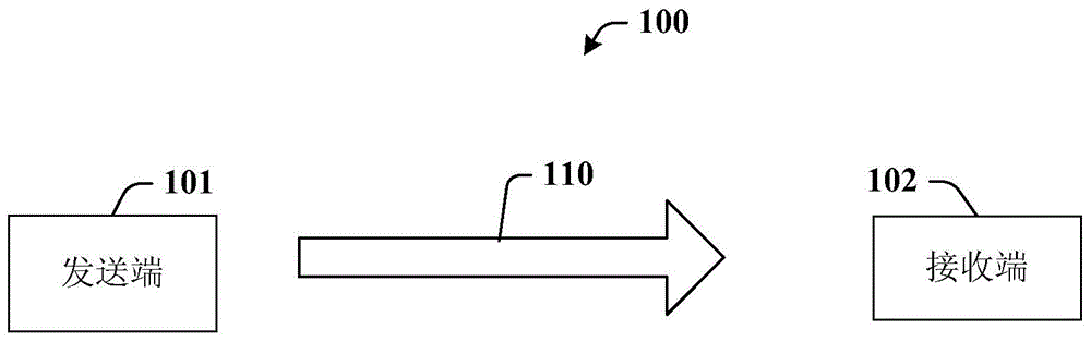
[0078] The sending and receiving process of this embodiment can be implemented on various electronic devices. figure 1 A block diagram of an optical communication system according to an embodiment of the present invention is shown, and the communication system 100 includes a sending end 101 and a receiving end 102 . The transmitting end 101 sends an optical signal to the receiving end 102 . The sending end 101 can be implemented as various portable electronic devices. Examples of portable electronic devices include, but are not limited to, mobile phones, tablet computers, and dedicated communication terminals.

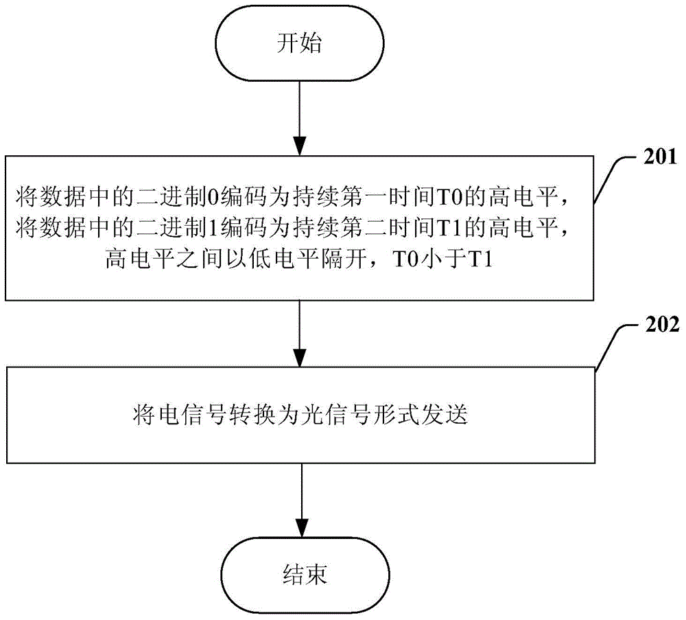
[0079] see figure 2 , is a flow chart of encoding and sending an optical signal according to the first embodiment of the present invention, and the process includes:

[0080] Step 201, encode the data to be sent into an electrical signal. Specifically, the binary 0 in the data is encoded as a high level for the first time T0, and the binary 1 in the data is encode...

no. 2 example

[0100] The sending and receiving process of this embodiment can be implemented on various electronic devices. The sending end can be implemented as various portable electronic devices. Examples of portable electronic devices include, but are not limited to, mobile phones, tablet computers, and dedicated communication terminals.

[0101] see Figure 5 , is a flow chart of encoding and sending an optical signal according to the second embodiment of the present invention, and the process includes:

[0102] Step 501, encode the data to be sent into an electrical signal. Specifically, the binary 0 in the data is encoded as a high level that lasts for the first time T0, and the binary 1 in the data is encoded as a high level that lasts for the second time T1, wherein T0 is greater than T1; between the high levels Separated by a low level as a separation mark. The data to be sent may be text, pictures, audio and / or video.

[0103] Figure 7 It is an exemplary coded electrical s...

no. 3 example

[0123] The sending and receiving process of this embodiment can be implemented on various electronic devices. The sending end can be implemented as various portable electronic devices. Examples of portable electronic devices include, but are not limited to, mobile phones, tablet computers, and dedicated communication terminals.

[0124] see Figure 8 , is a flow chart of encoding and sending an optical signal according to the third embodiment of the present invention, and the process includes:

[0125] Step 801, encode the data to be sent into an electrical signal. Specifically, the binary 0 in the data is coded as a low level that lasts for the first time T0, and the binary 1 in the data is coded as a low level that lasts for the second time T1, wherein T0 is less than T1; between the low levels Separated by a high level as a separation mark. The data to be sent may be text, pictures, audio and / or video.

[0126] Figure 10 It is an exemplary encoded electrical signal, ...


PUM


Abstract

The invention relates to a wireless signal decoding method, which is used for decoding an electric signal converted from a wireless signal. The wireless signal decoding method comprises the steps of: recording duration of each level of the electric signal; calculating an average value of m periods of maximum duration and an average value of n periods of minimum duration, wherein m and n are positive integers and are determined by referencing a distribution proportion value of first binary bit values to second binary bit values in data respectively; calculating judgment duration according to the first average value and the second average value; comparing the duration of each level with the judgment duration, and judging a binary bit value represented by the corresponding level according to the comparison result; and recovering data represented by the electric signal by integrating the binary bit values.

Description

technical field [0001] The present invention relates to the field of communications, in particular to a signal encoding and decoding method, device and system. Background technique [0002] Wireless optical communication is a new, short-distance and high-speed wireless optical communication technology developed on the basis of light-emitting diode (LED) technology. The basic principle of wireless optical communication is to use the characteristics of LED lamps to switch faster than fluorescent lamps and incandescent lamps, and to communicate through high-frequency flickering of LED light sources. Simply put, light represents a binary 1, and no light represents a binary 0. High-speed optical signals containing digital information can obtain information through photoelectric conversion. Wireless optical communication technology can be used to make wireless optical encryption keys because its data is not easy to be interfered and captured, and optical communication equipment ...

Claims


Application Information

Patent Timeline
Patent Type & Authority Applications(China)
IPC IPC(8): H04B10/116H04L1/00
CPCG06K7/00H04B10/524H04B10/695H04B11/00H04L25/4902H04B10/11H04B10/502H04B10/516H04B10/0795
Inventor 不公告发明人
Owner KUANG CHI INTELLIGENT PHOTONIC TECH
Why Eureka
Try Eureka