Power tool

A tool, machine technology, applied in the field of hand-guided tools and machines, which can solve problems such as limitations

Active Publication Date: 2016-03-30
C.& E.泛音有限公司 +1
View PDF8 Cites 6 Cited by
  • Summary
  • Abstract
  • Description
  • Claims
  • Application Information

AI Technical Summary

Problems solved by technology

However, limitations of this description do not constitu

Method used


Image

  • Power tool
  • Power tool
  • Power tool

Examples


Embodiment Construction

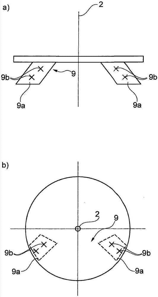
[0104] figure 1 Two views ( figure 1 a is the front view, figure 1 b is the top view). The torque transfer region 9 has two output surface regions 9a, each of which has a plurality of surface points 9b. The torque transmission region 9 serves to transmit the driving force from the machine tool to the tool device (not shown). The machine tool drives the tool device in a rotationally oscillating manner, whereby the tool device oscillates about a driven axis 2 which essentially coincides with the tool axis of rotation. The driven shaft 2 is a virtual geometric axis.

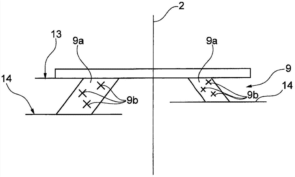
[0105] figure 2 A torque transmission region 9 of a machine tool is shown, which is designed to transmit the driving force from the machine tool to the tool device (not shown). The torque transmission region 9 has two output surface regions 9 a. A plurality of surface points 9b are shown on each output surface area 9a. The individual output area regions 9 a each extend between an upper boundary plane 13 and...


PUM


Abstract

The invention relates to a power tool, in particular a hand-held power tool, which has a tool receiving device that is movable, in particular in an oscillating manner, about an output axis (2). The tool receiving device is designed to hold a tool device on the power tool such that the output axis and a tool rotation axis substantially coincide. The tool receiving device has at least one torque transmission region (9) and a holding device (4a, 4b). In order to transmit a drive force to the tool device, the torque transmission region has at least two output surface regions (9a) that are at a distance from said output axis and each have a multiplicity of surface points. Here, tangent planes to said surface points are inclined with respect to an axial plane which includes said output axis. Furthermore, the tangent planes are inclined with respect to a radial plane which extends perpendicularly to the output axis. In this way, the output torque is transmitted reliably to the tool device by the power tool via the tool receiving device.

Description

[0001] The entire content of priority document DE202013006900.7 is hereby incorporated by reference into the present application. technical field [0002] The invention relates to a machine tool and in particular to a manually guided machine tool with a tool receiving device movable about an output shaft. Background technique [0003] The invention will be explained below primarily by way of example of a hand-guided machine tool, which has a tool receptacle that moves oscillatingly in rotation about an output shaft. However, such described limitations do not constitute limitations on the possible uses of such machine tools. [0004] The term "tool receiver" is also simply replaced herein by the term "tool receiver". But this should not be construed as a limitation either. [0005] A machine tool is a device having one or more drive motors and possibly one or more transmissions as well as at least one output shaft which has a geometric output axis. The tool receiver is arr...

Claims


Application Information

Patent Timeline
IPC IPC(8): B25F5/00B23Q3/12B24B23/04B24B45/00B27B19/00B27B5/30
CPCB27B5/32B24B45/006Y10T279/33B25F5/00B23B31/008B23B2231/48B23B31/10
Inventor 奥拉夫·克拉布恩德于尔根·布利克勒瓦尔特·托马施维斯基法比安·贝克S·德尔菲尼W·费尔曼B·卢彻M·博齐克T·马蒂斯D·格罗利蒙德
Owner C.& E.泛音有限公司
Why Eureka
Try Eureka