a free wardrobe

A wardrobe and free technology, applied in the field of furniture, can solve the problems that the wardrobe space is difficult to be fully utilized, and the storage space of the wardrobe is difficult to take and place, so as to achieve the effect of convenient retrieval, multiple functions, and free adjustment

Inactive Publication Date: 2018-01-19
奋钧智能(深圳)科技有限公司
View PDF7 Cites 0 Cited by
  • Summary
  • Abstract
  • Description
  • Claims
  • Application Information

AI Technical Summary

Problems solved by technology

[0002] At present, the floor height of ordinary residential quarters is generally 2.8 meters. After removing the thickness of the ceiling and floor, the height of the overall wardrobe can still reach about 2.5 meters. The storage space is difficult to access during actual use
In addition, the space size of each cabinet in a traditional wardrobe is fixed, making it difficult to fully utilize the space in the wardrobe.

Method used


Image

  • a free wardrobe
  • a free wardrobe
  • a free wardrobe

Examples


Embodiment 1

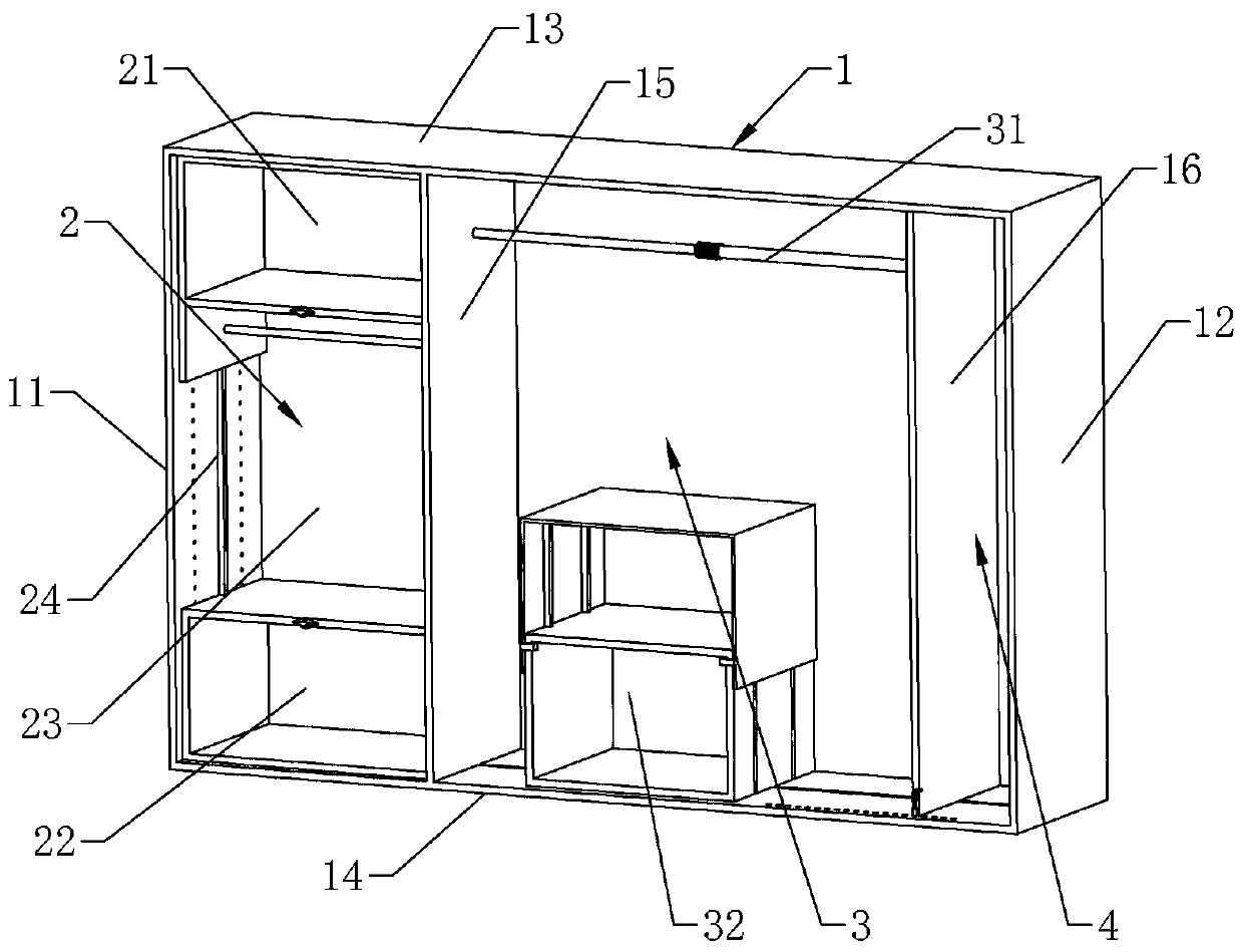
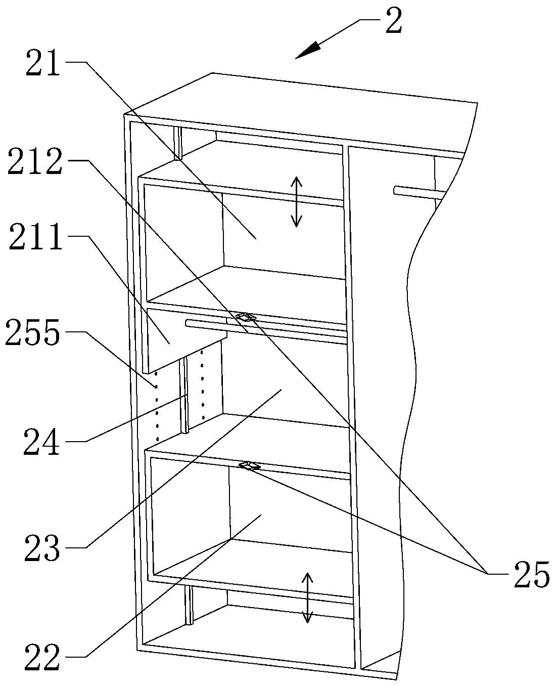
[0032] according to Figure 1 to Figure 8 As shown, a free wardrobe includes: a cabinet body 1 and a lifting area 2 inside the cabinet body 1, a combination area 3 and a long object area 4; the cabinet body 1 includes, the first side wall 11 and the second side wall on both sides 12. The top plate 13 and bottom plate 14 at the upper and lower ends, as well as the fixed wall plate 15 and the movable wall plate 16 inside; the movable wall plate 16 is connected with the top plate 13 and the bottom plate 14 through a translation mechanism 17, and has the function of parallel movement in the cabinet body 1, And change the size of the combined area 3 and the long object area 4 by moving; the lifting area 2 is the area formed by the first side wall 11, the top plate 13, the bottom plate 14 and the fixed wall plate 15, including the first mobile cabinet at the upper end of the lifting area 2 21. The second mobile cabinet 22 at the lower end of the lifting area 2 and the clothes hangin...

Embodiment 2

[0040] The difference from the above-mentioned embodiment 1 is that, according to Figure 7 As shown, at least two movable cabinets 32 are arranged in the combination area 3 , and the movable cabinets 32 include at least one floating cabinet 322 . To further enhance the adjustable performance of the storage space in the combined area 3.

Embodiment 3

[0042] The difference from the above-mentioned embodiment 1 is that, according to Figure 8 As shown, the first mobile cabinet 21 or the second mobile cabinet 22 is provided with a gas spring 26 on the connecting side of the first side wall 11 and the fixed wall plate 15 respectively, so that the first mobile cabinet 21 or the second mobile cabinet 22 is moved. A certain pulling force or pushing force is provided by the gas spring 26, thereby making the operator more labor-saving, and also avoiding the problem that there are too many items in the cabinet and the mobile cabinet cannot be raised or lowered.


PUM


Abstract

The invention relates to the field of furniture, in particular to a flexible wardrobe. The flexible wardrobe comprises a wardrobe body, a lifting area, a combined area and a long article area, wherein the lifting area, the combined area and the long article area are arranged inside the wardrobe body, the wardrobe body comprises a first side wall, a second side wall, a top plate, a base plate, a fixed wallboard and a movable wallboard, the first side wall and the second side wall are arranged on two sides, the top plate and the base plate are arranged at the upper end and the lower end, and the fixed wallboard and the movable wallboard are arranged inside; the movable wallboard is connected with the top plate and the base plate through transverse movement mechanisms and can move transversely in the wardrobe body to change the size of the space of the combined area and the size of the space of the long article area through movement; the lifting area is formed by the first side wall, the top plate, the base plate and the fixed wallboard and comprises a first movable chest at the upper end, a second movable chest at the lower end and a clothes hanging area between the first movable chest and the second movable chest, and the first movable chest and the second movable chest are connected with the first side wall and the fixed wallboard through lifting mechanisms and can rise and fall through the lifting mechanisms.

Description

technical field [0001] The invention relates to the field of furniture, in particular to a free wardrobe. Background technique [0002] At present, the floor height of ordinary residential quarters is generally 2.8 meters. After removing the thickness of the ceiling and floor, the height of the overall wardrobe can still reach about 2.5 meters. The storage space is difficult to access during actual use. In addition, the space size of each cabinet in a traditional wardrobe is fixed, making it difficult to fully utilize the space of the wardrobe. Contents of the invention [0003] The purpose of the present invention is to provide a free wardrobe in order to solve the problems in the background technology. [0004] Above-mentioned technical purpose of the present invention is achieved through the following technical solutions: [0005] A free wardrobe, comprising: a cabinet body and a lifting area inside the cabinet body, a combined area and a long object area; the cabine...

Claims


Application Information

Patent Timeline
Patent Type & Authority Patents(China)
IPC IPC(8): A47B61/00A47B51/00
CPCA47B51/00A47B61/00
Inventor 修兴祺郭世俊修兴洪廖莹
Owner 奋钧智能(深圳)科技有限公司
Why Eureka
Try Eureka