Die casting device of horizontal type cold chamber vacuum die casting machine and method for utilizing die casting device for die casting

A technology of vacuum die casting and cold chamber, applied in the field of die casting machines, can solve the problems of affecting the normal operation of parts, increasing the failure rate of parts, and taking a lot of time, so as to achieve the effects of easy setup and maintenance, long service life and good vacuum effect.

Inactive Publication Date: 2016-04-06
GUANGDONG HONGTU TECHNOLOGY (HOLDINGS) CO LTD
View PDF5 Cites 1 Cited by
  • Summary
  • Abstract
  • Description
  • Claims
  • Application Information

AI Technical Summary

Problems solved by technology

[0003] Existing vacuum die-casting generally extracts the gas in the cavity through a vacuum valve installed on the mold. This method has some disadvantages during use: 1) Due to the exhaust cross-sectional area of ​​the vacuum valve and the cross-sectional area of ​​the overflow slot It is difficult to quickly discharge a large amount of high-temperature fumes generated during pouring in the pressure chamber far away from the vacuum valve, because they need to flow along the runner, ingate, cavity, overflow groove, overflow groove, suction channel and vacuum The valve can only be discharged out of the cavity after waiting, the path is long and time-consuming
2) The high-temperature flue gas is discharged through the vacuum system, which will cause the temperature of some key components of the vacuum system such as valves and vacuum pumps to be too high, which will affect the normal operation of these components, increase the failure rate of parts, and reduce the reliability

Method used


Image

  • Die casting device of horizontal type cold chamber vacuum die casting machine and method for utilizing die casting device for die casting
  • Die casting device of horizontal type cold chamber vacuum die casting machine and method for utilizing die casting device for die casting
  • Die casting device of horizontal type cold chamber vacuum die casting machine and method for utilizing die casting device for die casting

Examples


Embodiment Construction

[0028] In order to make the object, technical solution and advantages of the present invention clearer, the present invention will be further described in detail below in conjunction with the accompanying drawings and embodiments. It should be understood that the specific embodiments described here are only used to explain the present invention, not to limit the present invention. In addition, the technical features involved in the various embodiments of the present invention described below can be combined with each other as long as they do not constitute a conflict with each other.

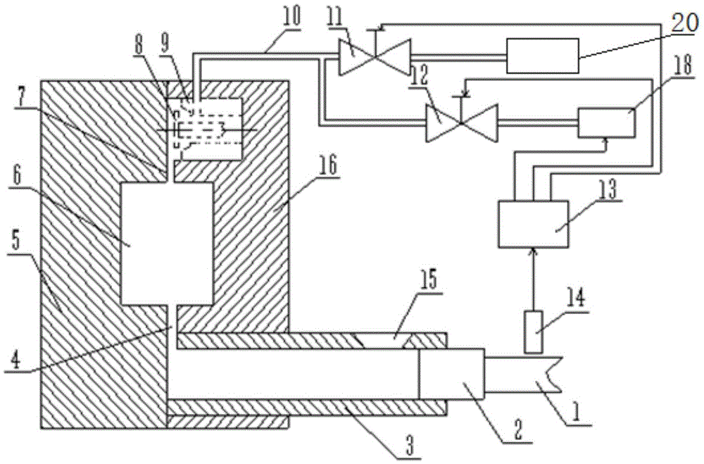
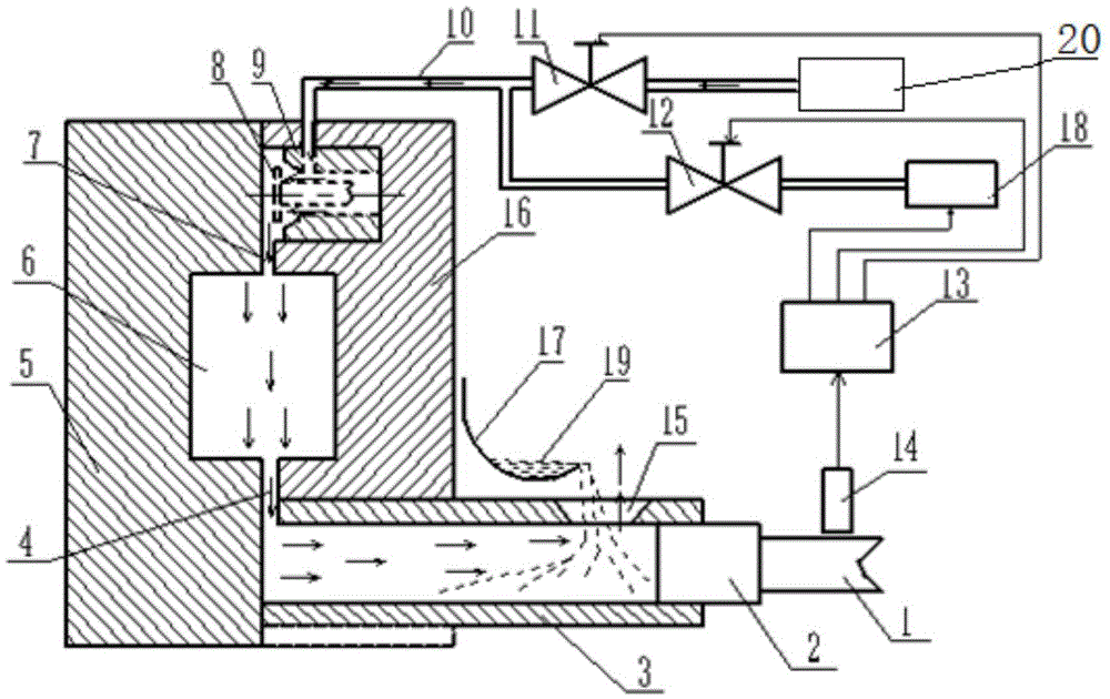
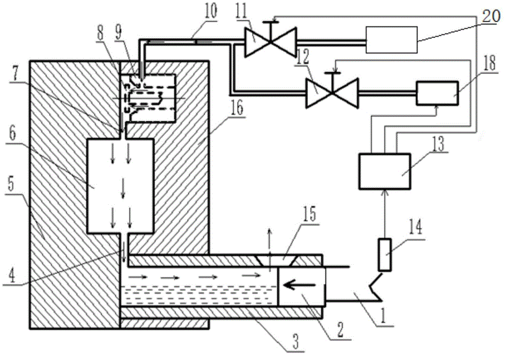
[0029] refer to Figure 1 ~ Figure 4 , a die-casting device of a horizontal cold chamber vacuum die-casting machine, comprising a pressure chamber 3, a die-casting mold, a vacuum valve, a punch 2, a shot rod 1, a first shut-off valve 11, a compressed air storage tank, a second shut-off valve 12, Vacuum system 18, control device 13 and displacement sensor 14, wherein,

[0030] The pressure cham...


PUM


Abstract

The invention discloses a die casting device of a horizontal type cold chamber vacuum die casting machine. The die casting device comprises a press chamber, a die casting die, a vacuum valve, a puncher pin, an ejection rod, a first stop valve, a compressed air storage tank, a second stop valve, a vacuum system, a control device and a displacement sensor. The die casting die comprises a fixed die body and a movable die body, and the fixed die body and the movable die body are matched to form a cavity, an inner sprue, an exhaust channel and a valve cavity. The vacuum valve is arranged at the position, in the fixed die body, of the valve cavity and connected with the first stop valve through a valve connecting pipe. The first stop valve is connected with the compressed air storage tank. A sprue gate is arranged on the press chamber. The control device is used for controlling running of the compressed air storage tank and the vacuum system and opening and closing of the first stop valve and the second stop valve. The die casting device has the advantages of being good in vacuum effect, easy and convenient to arrange and maintain, low in fault rate and long in service life.

Description

technical field [0001] The invention belongs to the field of die-casting machines, and more specifically relates to a die-casting device of a horizontal cold-chamber vacuum die-casting machine and a die-casting method using the die-casting device. Background technique [0002] Vacuum die-casting technology is a casting forming method that uses a vacuum source to discharge the gas inside the mold cavity, and then fills the mold cavity with molten metal in this vacuum state. Vacuum die-casting inherits the advantages of ordinary die-casting methods, but it can greatly reduce the internal porosity defects of castings, and has a significant effect on improving the quality of castings, so it has been widely used. [0003] Existing vacuum die-casting generally extracts the gas in the cavity through a vacuum valve installed on the mold. This method has some disadvantages during use: 1) Due to the exhaust cross-sectional area of ​​the vacuum valve and the cross-sectional area of ​​t...

Claims


Application Information

Patent Timeline
Patent Type & Authority Applications(China)
IPC IPC(8): B22D17/14B22D17/10
CPCB22D17/14B22D17/10
Inventor 徐飞跃张百在余亮汪学阳黄志垣安肇勇万里
Owner GUANGDONG HONGTU TECHNOLOGY (HOLDINGS) CO LTD
Why Eureka
Try Eureka