
Method for machining inner shape of vibration disc through digital controlled lathe

A technology of CNC lathe and machining vibration, which is applied in the field of inner shape machining of vibrating discs, can solve the problems of high cost, low efficiency and difficult quality assurance, and achieve the effect of low cost, high efficiency and quality assurance.

Inactive Publication Date: 2016-04-06
GUANGDONG COLLEGE OF BUSINESS & TECH
View PDF8 Cites 1 Cited by
  • Summary
  • Abstract
  • Description
  • Claims
  • Application Information

AI Technical Summary

Problems solved by technology

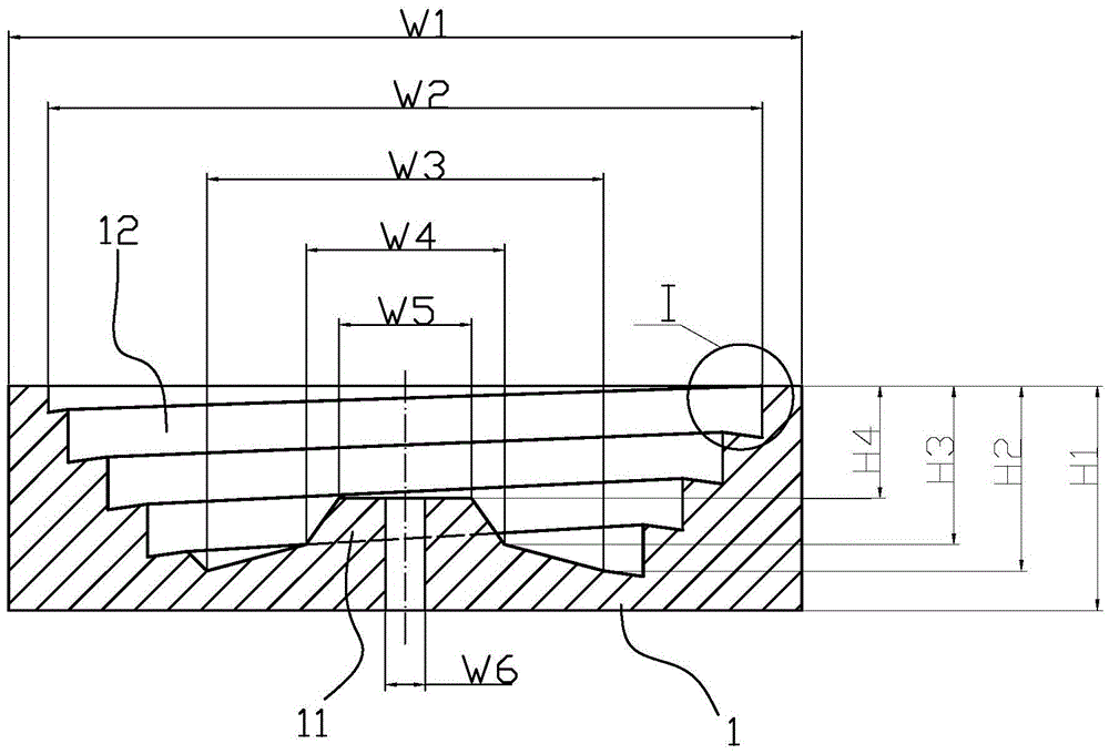
At present, in actual production, the vibrating plate 1 of this specification is mostly made by welding, but this method has defects such as low efficiency, difficult quality assurance and high cost; another vibrating plate 1 of this specification The manufacturing method is processed by a five-axis machining center. Although the quality can be guaranteed, for mass production, its efficiency is low and the cost is also high

Method used


Image

  • Method for machining inner shape of vibration disc through digital controlled lathe
  • Method for machining inner shape of vibration disc through digital controlled lathe
  • Method for machining inner shape of vibration disc through digital controlled lathe

Examples


Embodiment Construction

[0018] Now in conjunction with the accompanying drawings, the preferred embodiments of the present invention will be described in detail.

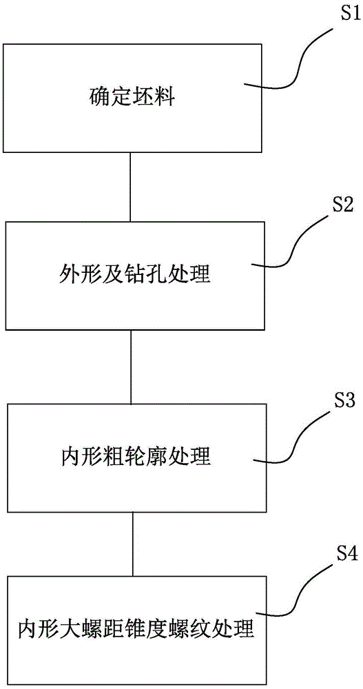
[0019] see Figures 2 to 3e , figure 2 It is a schematic flow chart of the processing method of the vibrating plate of the present invention. Figure 3a to Figure 3e It is a schematic representation of the process of processing a vibrating disc using the vibrating disc processing method of the present invention, wherein, Figure 3a The blank structure is shown; Figure 3b Turning face and outer circle treatment are shown; Figure 3c Shows the turning face and outer circle and drilling processing; Figure 3d Inner shape rough contour processing is shown; Figure 3e An internal high pitch taper thread treatment is shown.

[0020] The present invention proposes a processing method of a vibrating disc, which comprises steps:

[0021] S1. Determine the blank size. Specifically, using an electric saw to cut the material, determine the s...


PUM


Abstract

The invention relates to a method for machining the inner shape of a vibration disc through a digital controlled lathe. The method includes the steps that rough sketch treatment is carried out on the inner shape of a workpiece; and inner shape coarse pitch taper threaded treatment is carried out on the workpiece obtained after inner shape rough sketch treatment. By means of the method, the quality can be guaranteed, efficiency is high, and cost is low.

Description

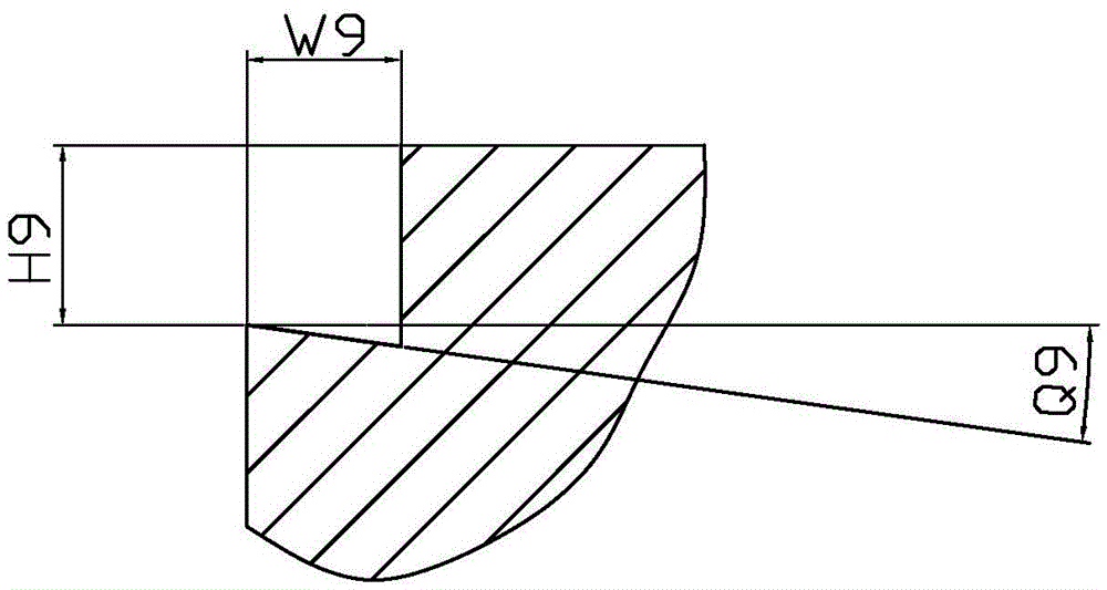
technical field [0001] The invention relates to an inner shape processing of a vibrating plate, in particular to a method for machining the inner shape of an integral vibrating plate with a numerical control lathe. Background technique [0002] see Figure 1a and 1b The vibrating plate 1 of a specification shown is made of aluminum alloy, and its outline dimensions are: the diameter W1 is 120 mm, and the thickness H1 is 34 mm. The inner structure of the vibrating plate 1 is a tapered thread 12, and there is a boss 11 in the middle of the bottom. The specific dimensions of the vibrating plate 1 are: the diameter W2 is 108 mm, the diameter W3 is 60 mm, the diameter W4 is 30 mm, and the diameter W5 is 20 mm; the thickness H2 is 28 mm, the thickness H3 is 24 mm, and the thickness H4 is 17 mm. The diameter W6 of the central hole is 6 millimeters. The pitch of the taper thread 12 of the vibrating plate 1 is larger, W9=H9=6 millimeters, and it is a left-handed taper thread from ...

Claims


Application Information

Patent Timeline
IPC IPC(8): B23B1/00
CPCB23B1/00
Inventor 蓝宪
Owner GUANGDONG COLLEGE OF BUSINESS & TECH
Learn More