Cabinet door illuminating system of horizontal injection molding machine

A lighting system and injection molding machine technology, applied in the field of cabinet door lighting system, can solve the problems of lighting system not working, poor electrical conductivity, wire damage, etc., and achieve the effect of convenient opening and closing of movable doors, saving time, and prolonging service life

Inactive Publication Date: 2016-04-06
TIANJIN BINPU PRODIVITY PROMOTION
View PDF0 Cites 2 Cited by
  • Summary
  • Abstract
  • Description
  • Claims
  • Application Information

AI Technical Summary

Problems solved by technology

[0002] The injection molding machine mainly processes thermosetting or thermoplastic plastics into rough plastic products through molds. The injection molding machines include three types: vertical, horizontal and all-electric. The lighting system of the bedroom injection molding machine is set on the cabinet door, and the outside of the cabinet door There is a control device for the lighting system. There is a wire connected between the control device and the lighting device. The wire must be bent during the opening and closing of the cabinet door, and the frequency of opening and closing the cabinet door is high, so it is used for a long time. It will cause serious damage to the wires, and even lead to poor conduction, making the lighting system unable to work and affecting processing and production

Method used

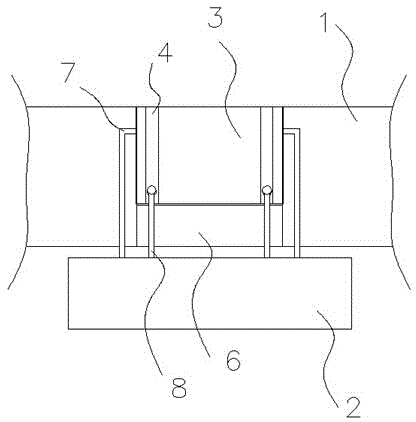
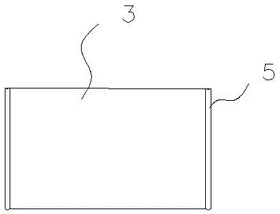
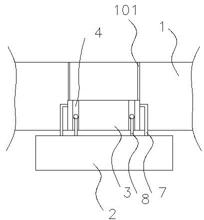

Image

  • Cabinet door illuminating system of horizontal injection molding machine
  • Cabinet door illuminating system of horizontal injection molding machine
  • Cabinet door illuminating system of horizontal injection molding machine

Examples


Embodiment Construction

[0011] In order to make the object, technical solution and advantages of the present invention clearer, the present invention will be further described in detail below in conjunction with the accompanying drawings and embodiments. It should be understood that the specific embodiments described here are only used to explain the present invention, not to limit the present invention.

[0012] In describing the present invention, it should be understood that the terms "longitudinal", "transverse", "upper", "lower", "front", "rear", "left", "right", "vertical", The orientations or positional relationships indicated by "horizontal", "top", "bottom", "inner", "outer", etc. are based on the orientations or positional relationships shown in the drawings, and are only for the convenience of describing the present invention, rather than indicating or It should not be construed as limiting the invention by implying that a referenced device or element must have a particular orientation, be...


PUM


Abstract

The invention relates to a cabinet door illuminating system of a horizontal injection molding machine. The cabinet door illuminating system comprises a movable door and a workbench. Two hydraulic supporting rods are arranged in the middle of the workbench. The two hydraulic supporting rods are fixed to the two sides of the movable door respectively. The movable door is a transparent door. Two longitudinal grooves are symmetrically formed in the movable door. Both the two ends of each groove are communicated with the outside. L-shaped supporting poles matched with the grooves are arranged on the workbench. Illuminating devices are arranged on the L-shaped supporting poles. One parts of the illuminating devices extend into the grooves. Two inward-protruding sliding rails are symmetrically arranged on the two sides of the movable door respectively. Two sliding grooves matched with the sliding rails are formed in an injection molding machine body. The two sliding rails are located on the inner sides of two hydraulic supporting poles respectively. A baffle is arranged under the movable door of the injection molding machine body and located on the rear side of the movable door. The rear side face of the movable door and the front side face of the baffle are located on the same plane. The cabinet door illuminating system is novel in design and flexible in operation, and has extensive practical value.

Description

technical field [0001] The invention relates to the technical field of vinyl equipment, in particular to a cabinet door lighting system for a horizontal injection molding machine. Background technique [0002] The injection molding machine mainly processes thermosetting or thermoplastic plastics into rough plastic products through molds. The injection molding machines include three types: vertical, horizontal and all-electric. The lighting system of the bedroom injection molding machine is set on the cabinet door, and the outside of the cabinet door There is a control device for the lighting system. There is a wire connected between the control device and the lighting device. The wire must be bent during the opening and closing of the cabinet door, and the frequency of opening and closing the cabinet door is high, so it is used for a long time. It will cause serious damage to the wires, and even poor conduction, which will make the lighting system unable to work and affect p...

Claims


Application Information

Patent Timeline
Patent Type & Authority Applications(China)
IPC IPC(8): B29C45/17E06B3/44F21V33/00F21W131/403
Inventor 由玉泉
Owner TIANJIN BINPU PRODIVITY PROMOTION
Why Eureka
Try Eureka