Radial bogie mechanism

A technology of radial bogies and frames, applied in the design and manufacture of rolling stock bogies, and in the field of rolling stock structure design, to achieve the effects of simplified structure, increased adhesion utilization, and reliable mechanical properties

Inactive Publication Date: 2016-04-06
SOUTHWEST JIAOTONG UNIV
View PDF8 Cites 3 Cited by
  • Summary
  • Abstract
  • Description
  • Claims
  • Application Information

AI Technical Summary

Problems solved by technology

[0003] The purpose of the present invention is to provide a radial bogie mechanism, which can effectively solve the problems existing in the radial bogie mechanism in the form of sub-frames

Method used


Image

  • Radial bogie mechanism
  • Radial bogie mechanism
  • Radial bogie mechanism

Examples


Embodiment Construction

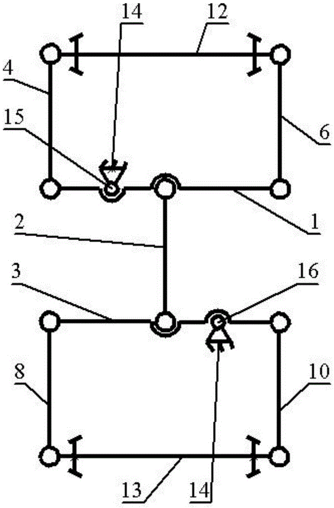
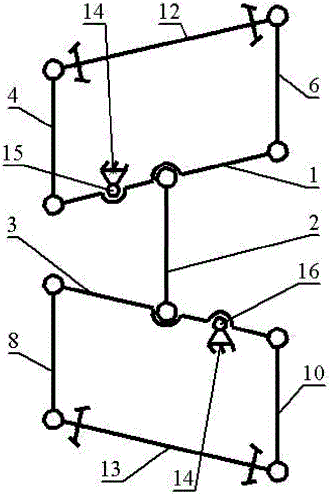
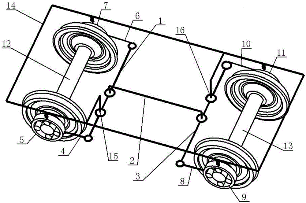
[0016] The present invention will be further described below in conjunction with accompanying drawing:

[0017] A radial bogie mechanism, comprising 12 wheelsets of the front axle and 13 wheelsets of the rear axle 14 supported by secondary springs, the left and right ends of the 12 wheelsets of the front axle are respectively provided with a left front axle box 5 and a right front axle Box 7, the left and right ends of rear axle 13 wheel pairs are respectively provided with left rear axle box 9, right rear axle box 11, and the left and right ends of front beam 1 are respectively provided with left front tie rod 4, right front tie rod 6, rear The left and right ends of the crossbeam 3 are respectively provided with a left rear tie rod 8 and a right rear tie rod 10, and a coupling rod 2 is provided between the front crossbeam 1 and the rear crossbeam 3; one end of the left front tie rod 4 is hinged with the left front axle box 5, and the other One end is hinged with the left end...


PUM


Abstract

The invention discloses a radial bogie mechanism, which relates to the technical field of motor vehicle structures and can effectively solve problems of the traditional bogie radial mechanism in the form of a deputy frame. One end of a left front pull rod is hinged on a left front axle box; the other end of the left front pull rod is hinged at the left end of a front cross beam; one end of a right front pull rod is hinged on a right front axle box; the other end of the right front pull rod is hinged at the right end of the front cross beam; one end of a left rear pull rod is hinged on a left rear axle box; the other end of the left rear pull rod is hinged at the left end of a rear cross beam; one end of a right rear pull rod is hinged on a right rear axle box; the other end of the right rear pull rod is hinged at the right end of the rear cross beam; the front cross beam is hinged on the left of the center of a frame; the rear cross beam is hinged on the right of the center of the frame; and the front cross beam is connected with the rear cross beam through a coupling rod so as to realize linkage between wheel pairs. As each wheel pair moves towards a radial position when a bogie passes through a curve, the radial bogie mechanism is beneficial for reducing an attack angle between a wheel rim and a steel rail so that the wear of the wheel rim is reduced and the adhesiveness of a motor vehicle on the curve is improved. The radial bogie mechanism is mainly used for bogies of motor vehicles or trucks.

Description

technical field [0001] The invention belongs to the technical field of locomotive and vehicle structure design, in particular to the technical field of design and manufacture of locomotive and vehicle bogies. Background technique [0002] During the operation of railway rolling stock in the curved section, the wheel-rail creep force realizes the radial occupation of the wheel set on the curve through the radial adjustment mechanism, which can effectively reduce the wheel-rail friction and wear. The radial bogie in the form of sub-frame The more famous structures are the Scheffel bogie in South Africa and the HTCR radial bogie in the United States. Please refer to the article "Unconventional Bogie Designs-Their Practical Basis and Historical Background" and the radial bogie disclosed in Chinese patent CN03148641.X. The use directions of these two bogies are different. Since there is no good independent property right of radial bogies in my country, it needs to be authorized b...

Claims


Application Information

Patent Timeline
Patent Type & Authority Applications(China)
IPC IPC(8): B61F5/38B61F5/48B61F5/22
CPCB61F5/22B61F5/38B61F5/48
Inventor 史炎马卫华
Owner SOUTHWEST JIAOTONG UNIV
Why Eureka
Try Eureka