A multi-tube energy-saving heat accumulator

A multi-tube, heat accumulator technology, applied in the direction of heat storage equipment, heat exchanger types, indirect heat exchangers, etc., can solve the problem of low heat exchange efficiency of low-flow materials, inability to control material temperature, and small heat storage To achieve the effect of improving heat storage capacity and cooling efficiency, increasing heat storage, and increasing heat exchange area

Inactive Publication Date: 2018-04-13
SOUTH CHINA UNIV OF TECH
View PDF8 Cites 0 Cited by
  • Summary
  • Abstract
  • Description
  • Claims
  • Application Information

AI Technical Summary

Problems solved by technology

[0003] Aiming at the problems of small heat storage, low heat transfer efficiency of low-flow materials, inability to control material temperature, and material pollution, a multi-tube energy-saving heat accumulator with cold and heat shunting is proposed, which improves the heat storage to a certain extent. , so that the heat exchange efficiency of low-flow materials is greatly improved, and the cold and hot pipes are realized to solve the problem of material pollution, and at the same time, the fluid temperature is controllable

Method used


Image

  • A multi-tube energy-saving heat accumulator
  • A multi-tube energy-saving heat accumulator
  • A multi-tube energy-saving heat accumulator

Examples


Embodiment Construction

[0028] The purpose of the present invention will be further described in detail through specific examples below, and the examples cannot be repeated here one by one, but the implementation of the present invention is not therefore limited to the following examples.

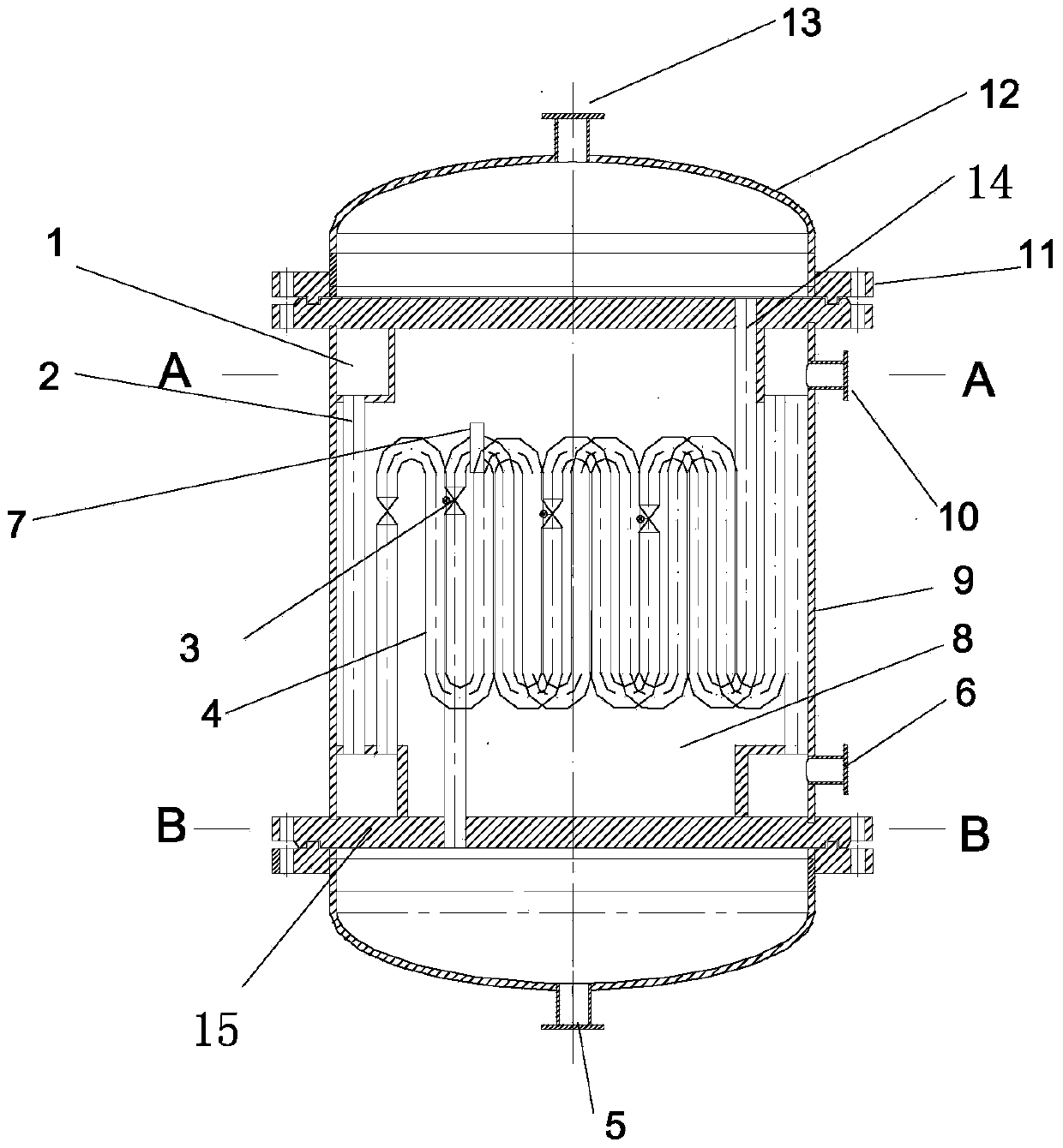
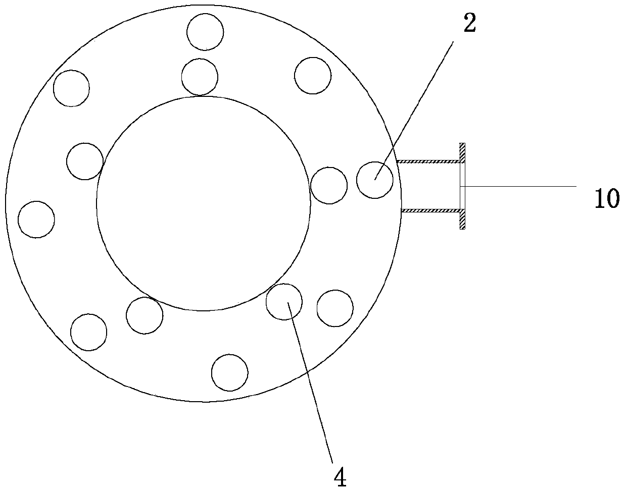
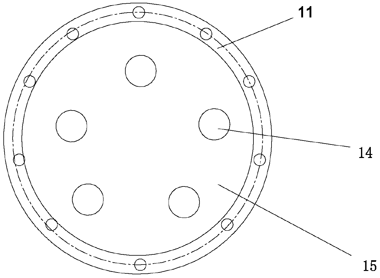
[0029] Such as Figure 1 to Figure 3 As shown, a multi-tube-pass energy-saving heat accumulator with cold and heat splitting includes a vertically arranged cylindrical cylinder 9, two hemispherical heads 12 connected to the upper and lower ends of the cylinder 9 through flanges 11, Between the upper and lower ends of the cylinder 9 and the two hemispherical heads 12, there is also a cylinder end plate 15 that isolates the inner cavity of the cylinder 9 from the inner cavity of the hemispherical heads 12, and is located at the upper end of the cylinder 9. The hemispherical head 12 is provided with a thermal fluid outlet 13, and the hemispherical head 12 located at the lower end of the cylinder 9 is provided with a ...


PUM


Abstract

The invention discloses a cold-hot diffluent multi-pipe-pass energy-saving heat accumulator. The heat accumulator comprises a cylindrical barrel arranged vertically and two hemispherical heads connected to the upper end and the lower end of the barrel through flanges respectively. Barrel end plates are further arranged among the upper end and the lower end of the barrel and the two hemispherical heads. The hemispherical head located at the upper end is provided with a hot fluid outlet, and the hemispherical head located at the lower end is provided with a hot fluid inlet. Annular diversion grooves are formed in the upper end and the lower end of the inner wall of the barrel respectively, and a plurality of cold fluid straight pipes and a plurality of cold fluid coil pipes are arranged between the two annular diversion grooves. A cold fluid inlet and a cold fluid outlet are formed in the outer circumferential wall of the barrel. A plurality of hot fluid coil pipes are arranged between the two barrel end plates uniformly. The parts, among the hot fluid coil pipes, the cold fluid straight pipes and the cold fluid coil pipes, of the spaces are filled with heat storage materials. The cold-hot diffluent multi-pipe-pass energy-saving heat accumulator enables the heat storage process and the heating process to become automatic and controllable, the material flow pollution problem of traditional heat accumulators is solved, and meanwhile the heat exchange efficiency and the heat storage capacity are improved significantly.

Description

technical field [0001] The invention relates to the technical field of heat transfer and energy saving, in particular to a multi-tube energy-saving heat accumulator with cold and heat split flow. Background technique [0002] With the aggravation of energy crisis and environmental pollution, people pay more and more attention to saving energy, and various energy-saving technologies have been widely used by people. As a kind of energy-saving equipment, heat accumulator can store heat and use heat flexibly. At the same time, it has the advantages of good performance, high reliability, high heat storage density and almost constant heat exchange temperature. The traditional heat accumulator has no structural After careful research, the heat storage is not large, the heat exchange efficiency of low-flow materials is not high, and the temperature of the materials cannot be controlled, and the heat accumulator does not separate the cold and hot fluids in structure, which cannot sol...

Claims


Application Information

Patent Timeline
Patent Type & Authority Patents(China)
IPC IPC(8): F28D20/00
CPCF28D20/00Y02E60/14
Inventor 方利国徐培鑫彭艳君
Owner SOUTH CHINA UNIV OF TECH
Why Eureka
Try Eureka