Cell set voltage acquisition board tool tester
A technology of voltage acquisition board and battery pack, which is applied in the direction of instruments, measuring electronics, measuring devices, etc., can solve the problems of poor detection reliability and low efficiency, and achieve the effects of improved detection efficiency, simple circuit structure, and low cost
- Summary
- Abstract
- Description
- Claims
- Application Information
AI Technical Summary
Problems solved by technology
Method used
Image
Examples
specific Embodiment approach 1
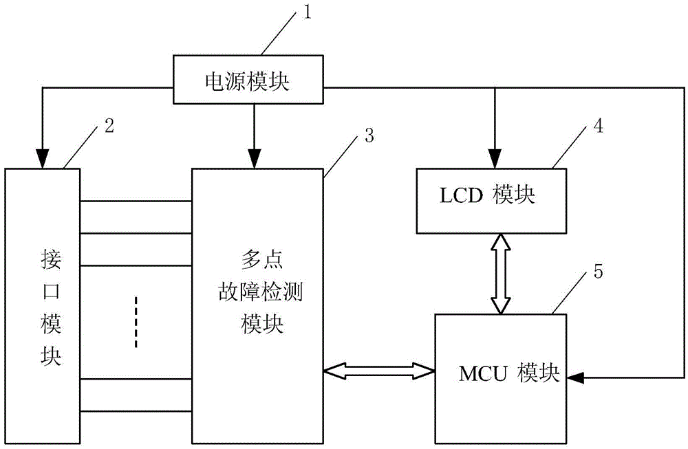
[0032] Specific implementation mode one: see figure 1 with 2 Describe this embodiment mode, a kind of battery pack voltage acquisition board tooling tester described in this embodiment mode, it comprises power supply module 1, interface module 2, multi-point fault detection module 3, LCD module 4 and MCU module 5;
[0033] The power supply module 1 is used to provide power to the interface module 2, the multi-point fault detection module 3, the LCD module 4 and the MCU module 5;
[0034] The interface module 2 is used to connect with the battery pack voltage acquisition signal input terminal on the voltage acquisition board to be measured;
[0035] The multi-point fault detection module 3 is used to perform fault detection on multiple points on the voltage acquisition board to be measured through the interface module 2, and send a fault detection signal;
[0036] The MCU module 5 is used to control the multi-point fault detection module 3, receive and process the fault detec...
specific Embodiment approach 2
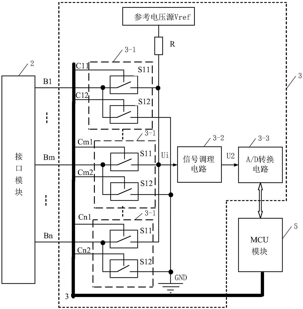
[0039] Specific implementation mode two: see figure 1 with 2 This embodiment is described. The difference between this embodiment and the battery pack voltage acquisition board tooling tester described in the first embodiment is that the multi-point fault detection module 3 includes n fault detection units 3-1, piezoresistor R, signal conditioning circuit 3-2 and A / D conversion circuit 3-3; n is a positive integer greater than or equal to 2;
[0040] The data signal input terminals of the 1st to nth fault detection units 3-1 are respectively connected with n battery pack voltage acquisition signal input terminals on the voltage acquisition board to be tested,
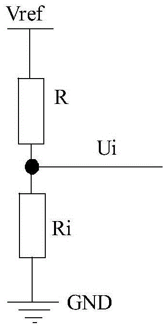
[0041] The first data signal output end of each fault detection unit 3-1 is connected with one end of the voltage dividing resistor R and the data signal input end of the signal conditioning circuit 3-2 at the same time, and the data signal output end of the signal conditioning circuit 3-2 is connected with A The data...
specific Embodiment approach 3
[0047] Embodiment 3: The difference between this embodiment and the tooling tester for a battery pack voltage acquisition board described in Embodiment 2 is that each fault detection unit 3-1 includes a detection switch S11 and a detection switch S12;
[0048] The control signal input terminals of the detection switch S11 and the detection switch S12 are both used to receive the control signal output by the MCU module 5;
[0049] One end of the detection switch S11 and one end of the detection switch S12 are simultaneously connected to a data signal output end of the interface module 2,
[0050] The other end of the detection switch S11 is used as the first data signal output end of the fault detection unit 3-1,
[0051] The other end of the detection switch S12 is used as the second data signal output end of the fault detection unit 3-1,
[0052] One end of the detection switch S11 is the data signal input end of the fault detection unit 3-1.
PUM
 Abstract
Description
Claims
Application Information
 - R&D
- Intellectual Property
- Life Sciences
- Materials
- Tech Scout
- Unparalleled Data Quality
- Higher Quality Content
- 60% Fewer Hallucinations
Browse by: Latest US Patents, China's latest patents, Technical Efficacy Thesaurus, Application Domain, Technology Topic, Popular Technical Reports.
© 2025 PatSnap. All rights reserved.Legal|Privacy policy|Modern Slavery Act Transparency Statement|Sitemap|About US| Contact US: help@patsnap.com


