Shading tape, backlight module, display device and cutting die

A technology of shading tape and backlight module, which is applied in optics, nonlinear optics, instruments, etc. It can solve the problems of affecting the shading effect of shading tape, light leakage of liquid crystal display devices, etc., achieve air pressure balance, prevent air pressure difference, and avoid adsorption and bonding Effect

Inactive Publication Date: 2016-04-06
BOE TECH GRP CO LTD +1
View PDF4 Cites 9 Cited by
  • Summary
  • Abstract
  • Description
  • Claims
  • Application Information

AI Technical Summary

Problems solved by technology

[0004] However, the existence of the gap will affect the light-shielding effect of the light-shielding tape, resulting in the problem of light leakage in the liquid crystal display device.

Method used


Image

  • Shading tape, backlight module, display device and cutting die
  • Shading tape, backlight module, display device and cutting die
  • Shading tape, backlight module, display device and cutting die

Examples


Embodiment Construction

[0033] The following will clearly and completely describe the technical solutions in the embodiments of the present invention with reference to the accompanying drawings in the embodiments of the present invention. Obviously, the described embodiments are only some, not all, embodiments of the present invention. Based on the embodiments of the present invention, all other embodiments obtained by persons of ordinary skill in the art without making creative efforts belong to the protection scope of the present invention.

[0034] In describing the present invention, it is to be understood that the terms "center", "upper", "lower", "front", "rear", "left", "right", "vertical", "horizontal", The orientations or positional relationships indicated by "top", "bottom", "inner", "outer", etc. are based on the orientations or positional relationships shown in the drawings, and are only for the convenience of describing the present invention and simplifying the description, rather than in...


PUM

PropertyMeasurementUnit
widthaaaaaaaaaa

Abstract

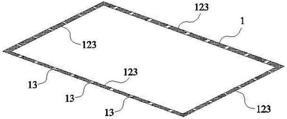
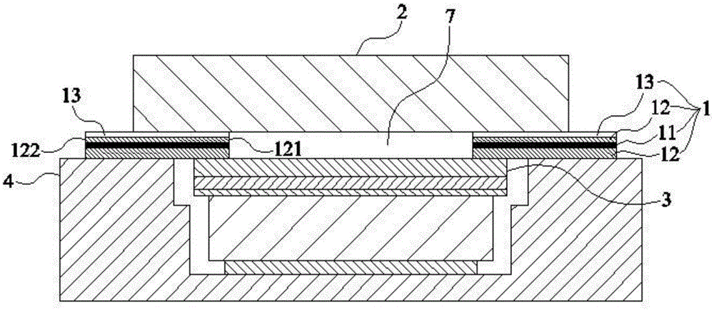
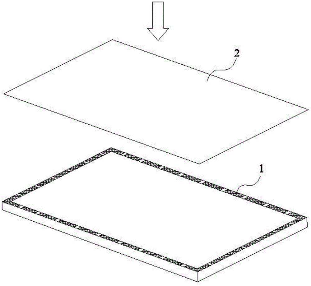
The invention discloses a piece of shading tape, a backlight module, a display device and a cutting die and relates to the technical field of display. By means of the shading tape, the backlight module, the display device and the cutting die, on the basis of preventing the liquid crystal display device from generating light leakage, the problems of adsorption and attachment of an optical film layer and a liquid crystal panel can be solved. The shading tape is in an annular shape and comprises a shading layer and glue layers arranged on the surfaces of the two sides of the shading layer, each glue layer comprises an inner side face and an outer side face, the glue layers are provided with air through grooves, and the air through grooves penetrate through the outer side faces and the inner side faces. The shading tape, the backlight module, the display device and the cutting die are used for fixing the liquid crystal panel to the backlight module.

Description

technical field [0001] The invention relates to the field of display technology, in particular to a light-shielding adhesive tape, a backlight module, a display device and a cutting die. Background technique [0002] In the current liquid crystal display device, the liquid crystal panel is usually bonded to the ring-shaped light-shielding tape in the backlight module, so as to realize the fixation with the backlight module. During assembly, the liquid crystal panel is gradually pressed down, and finally forms a closed cavity with the ring-shaped light-shielding tape and the optical film layer in the backlight module. During the process of pressing down the liquid crystal panel, part of the air in the cavity surrounded by the ring-shaped light-shielding tape will be discharged. Therefore, after the cavity is sealed, the air pressure in the cavity is lower than the air pressure outside the cavity, which will This causes the upper surface of the optical film layer to adhere to...

Claims


Application Information

Patent Timeline
Patent Type & Authority Applications(China)
IPC IPC(8): G02F1/1333G02F1/13357G02F1/13
CPCG02F1/1333G02F1/1303G02F1/1336
Inventor 高亮谭叶舟桑建孙海威禹璐
Owner BOE TECH GRP CO LTD
Why Eureka
Try Eureka