Charging disinfector with safety protection function

A technology of safety protection and disinfection cabinet, which is applied in the direction of emergency protection circuit device, protection that responds to overcurrent, emergency protection device that automatically disconnects, etc., and can solve the problems of large volume, inconvenient transportation, no leakage protection, operator injury, etc. problems, to achieve the effect of realizing automatic protection function, avoiding frequent contact, and improving safety performance

Active Publication Date: 2016-04-06
天津恒达文博科技股份有限公司
View PDF5 Cites 5 Cited by
  • Summary
  • Abstract
  • Description
  • Claims
  • Application Information

AI Technical Summary

Problems solved by technology

[0003] (1) There is no ultraviolet disinfection status prompt function and the protective function of automatically turning off the ultraviolet light. In extreme cases, it will cause harm to the operator, and the disinfection time cannot be set to automatically turn off the disinfection function
[0004] (2) Commonly used operation buttons are directly connected to 220V AC, which will cause harm to the operator in extreme cases, and there is no leakage protection function
[0005] (3) Only applicable to some specific models, and cannot charge multiple devices at the same time
[0006] (4) It is inconvenient to transport due to its large volume, and it is inconvenient to operate due to its high cabinet body.
[0007] (5) There is no charging status statistics and reminder function, so it is impossible to know the charging status of the equipment in the cabinet at this time

Method used


Image

  • Charging disinfector with safety protection function
  • Charging disinfector with safety protection function
  • Charging disinfector with safety protection function

Examples


Embodiment Construction

[0055]It should be noted that, in the case of no conflict, the embodiments of the present invention and the features in the embodiments can be combined with each other.

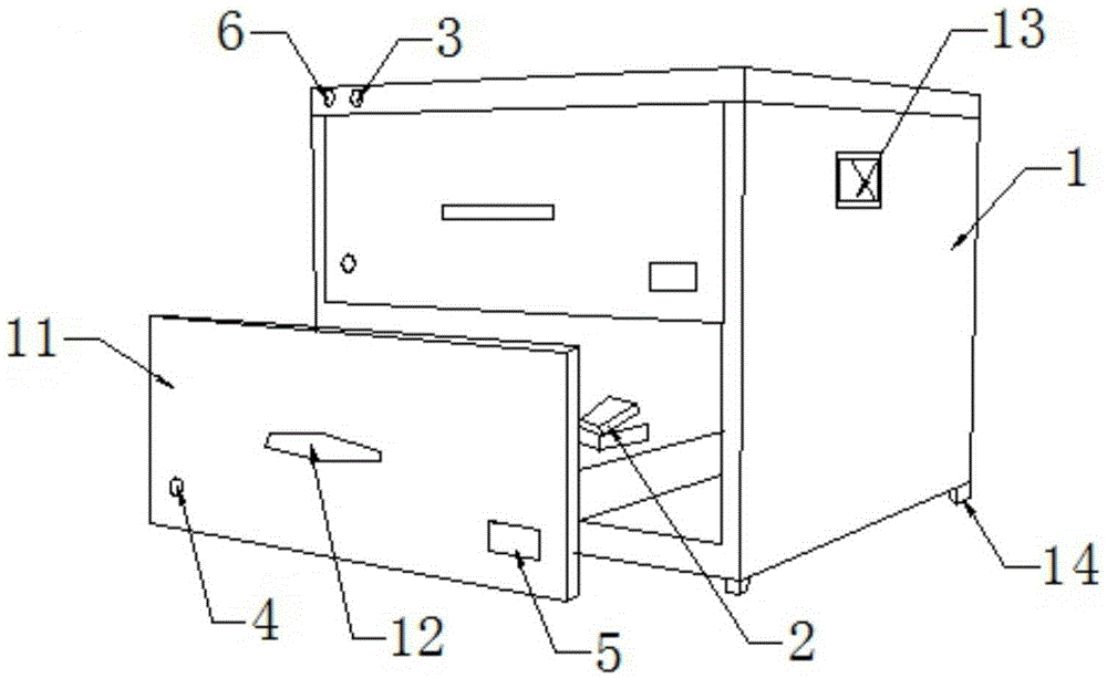
[0056] In describing the present invention, it should be understood that the terms "center", "longitudinal", "transverse", "upper", "lower", "front", "rear", "left", "right", " The orientations or positional relationships indicated by "vertical", "horizontal", "top", "bottom", "inner" and "outer" are based on the orientations or positional relationships shown in the drawings, and are only for the convenience of describing the present invention and Simplified descriptions, rather than indicating or implying that the device or element referred to must have a particular orientation, be constructed and operate in a particular orientation, and thus should not be construed as limiting the invention. In addition, the terms "first", "second", etc. are used for descriptive purposes only, and should not be understood a...


PUM


Abstract

The invention provides a charging disinfector with a safety protection function, which comprises a cabinet body and a power port, an air switch, a switching power supply, a switching power supply group, a multiplexer, charging seats, a limit switch, a disinfection timer, a disinfection switch button and an ultraviolet disinfection lamp arranged inside the cabinet body, wherein the power port is fixed on the side wall of the cabinet body; the power port outputs two ways of power lines via the air switch, one path is connected into the switching power supply and the other path is connected into the switching power supply group; the switching power supply group is electrically connected with the multiplexer, a power signal is inputted to the multiplexer, and multiple charging seats are correspondingly connected onto the multiplexer; the switching power supply is electrically connected with the ultraviolet disinfection lamp via the disinfection timer; and both the limit switch and the disinfection switch button are in signal connection with the disinfection timer. According to the charging disinfector with the safety protection function, through perfecting defects of the existing charging disinfector, the safety and the practicality of the charging disinfector are enhanced.

Description

technical field [0001] The invention belongs to the technical field of disinfection of electronic equipment chargers, and in particular relates to a stackable charging disinfection cabinet with a safety protection function and compatible with various models. Background technique [0002] As electronic equipment is used more and more widely, the demand for charging and disinfecting devices for electronic equipment is also increasing. The existing charging and disinfecting devices for electronic equipment generally have the following problems: [0003] (1) There is no UV disinfection status prompt function and the protection function of automatically turning off the UV lamp. In extreme cases, it will cause harm to the operator, and the disinfection time cannot be set to automatically turn off the disinfection function. [0004] (2) Commonly used operation buttons are directly connected to 220V AC, which will cause harm to the operator in extreme cases, and there is no leakage ...

Claims


Application Information

Patent Timeline
IPC IPC(8): G05B19/04H02H3/08H02H3/32
CPCG05B19/04H02H3/08H02H3/32
Inventor 韩国民
Owner 天津恒达文博科技股份有限公司
Why Eureka
Try Eureka