Rack and bundling machine

A rack and front rack technology, applied to agricultural machinery and implements, packaging, application, etc., can solve problems such as potential safety hazards, and achieve the effect of eliminating potential safety hazards and reducing power sources

Inactive Publication Date: 2017-03-15
GRASSLAND RES INST OF CHINESE ACAD OF AGRI SCI
View PDF7 Cites 0 Cited by
  • Summary
  • Abstract
  • Description
  • Claims
  • Application Information

AI Technical Summary

Problems solved by technology

However, when the hydraulic cylinder is damaged or the connection between the hydraulic cylinder and the front frame and the rear frame fails, the bale in the frame will push the rear frame away by itself, and the baler has safety in the process of baling the straw. Hidden danger

Method used


Image

  • Rack and bundling machine
  • Rack and bundling machine
  • Rack and bundling machine

Examples


Embodiment 1

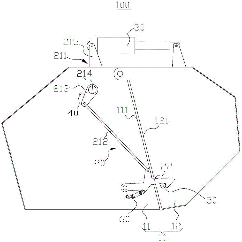
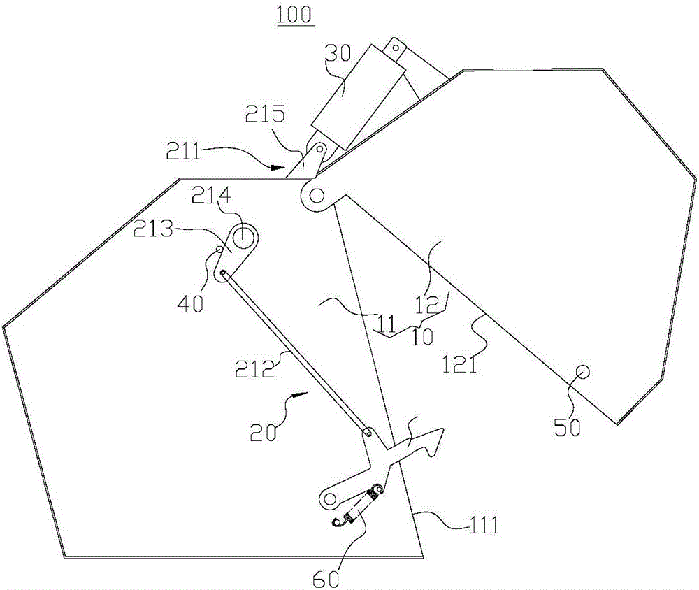
[0051] Such as figure 1 , figure 2 As shown, this embodiment provides a frame 100 , including a frame body 10 , a locking mechanism 20 and a hydraulic cylinder 30 .

[0052] The frame body 10 includes a front frame 11 and a rear frame 12, the top of the front frame 11 near the rear frame 12 is rotatably connected with the top of the rear frame 12 near the front frame 11 side, and the hydraulic cylinder 30 is used for The rear frame 12 is driven to rotate relative to the front frame 11 .

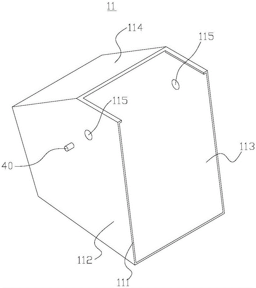
[0053] In this embodiment, specifically, as image 3 As shown, the front frame 11 is roughly a pentagonal prism structure, which is composed of two parallel pentagonal side plates and three connected peripheral plates 114 and a hollow structure with an opening on one side. The inclined first bonding surface 111 . Wherein, the two parallel pentagonal side plates are respectively the first side plate 112 and the second side plate 113 , and the first side plate 112 and the second side plate...

Embodiment 2

[0067] The rack 100 provided by the embodiment of the present invention has the same realization principle and technical effects as the aforementioned method embodiments. For brief description, for the parts not mentioned in the device embodiments, reference may be made to the corresponding methods in the aforementioned method embodiments. content.

[0068] In the above embodiment, the hydraulic cylinder 30 is not only the power source for the rotation of the rear frame 12, but also the power source for the action of the locking mechanism 20. During the process of the frame body 10 from the open state to the closed state, the locking mechanism may appear. 20 moves first and then the frame 12 rotates, which may lead to the phenomenon that the execution part 22 cannot cooperate with the locking part 50 .

[0069] For this reason, in this embodiment, as Figure 9 , Figure 10 As shown, further improvements are made to the limiting member 40 and the first connecting portion 213 ...

Embodiment 3

[0079] Such as Figure 15 As shown, the present embodiment provides a strapping machine 200, which includes a pick-up device 201, a strapping device 202, a transmission device 203 and the frame 100 in the above embodiment, and the strapping device 202 is located at the front of the frame 100 Inside the frame 11 , the pick-up device 201 is arranged on the lower side of the front frame 11 , and the front side of the front frame 11 is provided with a pull rod 205 .

[0080] The transmission device 203 is a chain, and the front frame 11 and the rear frame 12 are provided with a plurality of circumferentially distributed rollers 204, and the chain is used to drive all the rollers 204 to rotate.

[0081] During operation, the grass strips on the ground are picked up by the pick-up device 201 and sent into the frame 100. Under the action of the drum 204, the grass strips are rotated and gradually piled up, and finally bundled into bales by the rope binding device 202. During the ope...


PUM


Abstract

The invention provides a rack and a bundling machine and belongs to the field of agricultural machinery. The rack comprises a rack body, a locking mechanism and a hydraulic cylinder, wherein the locking mechanism is arranged on the rack body. the rack body comprises a front rack and a rear rack, the front rack is hinged to the rear rack, the hydraulic cylinder is used for driving the rear rack to rotate with respect to the front rack and making the rear rack and the front rack fit or separated. The rack body have an opening state and a closing state. The locking mechanism comprises a transmission part and an execution part, wherein the execution part is connected with the hydraulic cylinder through the transmission part. When the rack body is in a closing state, the hydraulic cylinder can drive the execution part to lock the front rack and the rear rack. When the hydraulic cylinder is damaged or connection between the front rack and the rear rack is invalid, a bale in the rack is not pushed away from the rear rack, and potential safety hazard existing in the bundling process can be effectively eliminated. The bundling machine provided with the rack has good safety performance.

Description

technical field [0001] The invention relates to the field of agricultural machinery, in particular to a frame and a tying machine. Background technique [0002] Very common in agricultural operations, the baler is a machine that prepares large bales. During operation, the grass strips on the ground are picked up by the pick-up device, and enter the baling chamber, and the grass strips are rotated into bales under the action of the roller. [0003] The frame in the existing baler generally includes a front frame and a rear frame. The front frame and the rear frame are rotatably connected to form a baling chamber. shelf opening or closing. However, when the hydraulic cylinder is damaged or the connection between the hydraulic cylinder and the front frame and the rear frame fails, the bale in the frame will push the rear frame away by itself, and the baler has safety in the process of baling the straw. Hidden danger. Contents of the invention [0004] The object of the pr...

Claims


Application Information

Patent Timeline
IPC IPC(8): A01F15/08
CPCA01F15/08
Inventor 布库焦巍孙启忠
Owner GRASSLAND RES INST OF CHINESE ACAD OF AGRI SCI
Why Eureka
Try Eureka