Air energy jet flow micro inflow type cosmetic instrument

An air energy and beauty instrument technology, which is applied to hypodermic injection devices, drug devices, other medical devices, etc., can solve the problems of uneven distribution of liquid medicine, waste, volatilization loss of liquid medicine, etc., and shorten the distance and time of air movement. , The effect of reducing tail volume and weight, improving skin condition

Active Publication Date: 2017-12-15
HUANGHE S & T COLLEGE
View PDF3 Cites 2 Cited by
  • Summary
  • Abstract
  • Description
  • Claims
  • Application Information

AI Technical Summary

Problems solved by technology

Existing cosmetology is usually to apply the cosmetic liquid on the skin surface, let the skin absorb heat to complete the cosmetic or micro plastic surgery, in the process of the cosmetic liquid penetrates into the skin through the pores of the skin and is absorbed, due to personal skin conditions, environment, etc. Conditions and factors of the medicinal liquid itself lead to different effects. The medicinal liquid may stay on the skin surface for a long time and absorb slowly, so that most of the medicinal liquid is wasted due to volatilization and loss, so that the expected therapeutic effect cannot be achieved; there is also a beauty treatment The method is to directly inject the liquid medicine into the skin by using a traditional syringe. This method will not only cause damage to the skin and bring pain to the patient, but also cause the depth and The dosage is different, and at the same time, the distribution of the medicinal liquid in the skin is not uniform, which is not conducive to controlling the treatment area, and also cannot achieve the expected therapeutic effect

Method used


Image

  • Air energy jet flow micro inflow type cosmetic instrument
  • Air energy jet flow micro inflow type cosmetic instrument
  • Air energy jet flow micro inflow type cosmetic instrument

Examples


Embodiment Construction

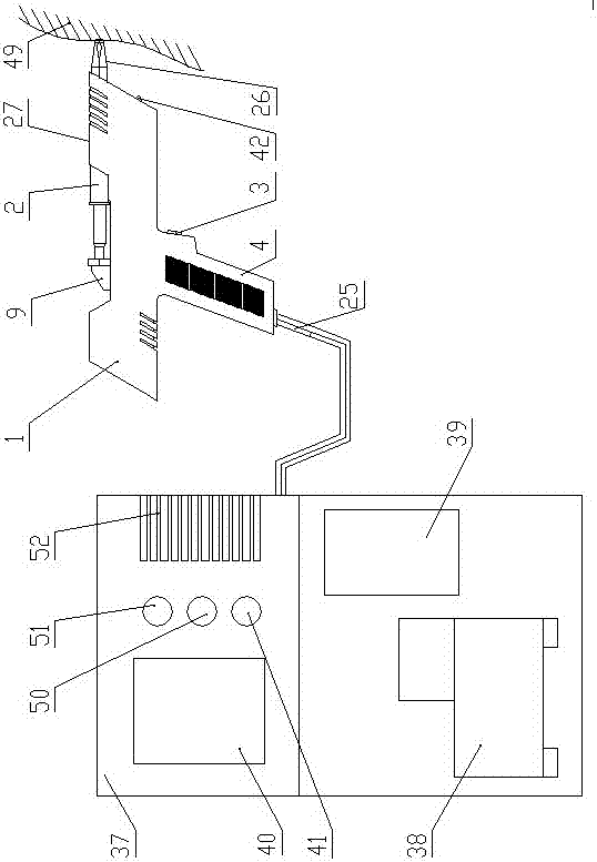
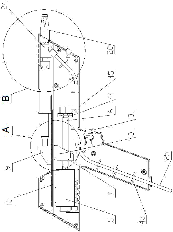
[0029] Such as Figure 1 to Figure 6 shown in figure 1 The right side of the right side is the forward direction of the present invention. The air energy jet micro-injection beauty instrument of the present invention includes a meso-gun shell 1, a syringe 2 and a key switch 3. The outer contour of the meso-gun shell 1 is pistol-shaped, and the syringe 2 Installed on the top of the meso gun shell 1, the key switch 3 is installed on the handle 4 of the meso gun shell 1, and also includes a control cabinet, a drive mechanism and a medicinal liquid injection mechanism installed on the meso gun shell 1,

[0030] The control cabinet comprises a cabinet 37, an air compressor 38 and a controller 39 located inside the cabinet 37, and a display screen 40, an air compressor control button 41, a display screen control button 50 and an LED light control button 51 are installed on the cabinet 37. 37 is provided with some cooling holes 52, the air compressor 38 communicates with the lower p...


PUM


Abstract

The invention discloses an air energy jet flow micro inflow type cosmetic instrument. The instrument comprises a mesogun shell, an injector, a key switch, a control cabinet, a driving mechanism installed on the mesogun shell and a liquid medicine injection mechanism. The control cabinet comprises an equipment cabinet, and an air compressor and a controller which are arranged inside the equipment cabinet; the driving mechanism comprises a gear motor, a lead screw, a nut, a nut connecting block, a push block and a baffle, the nut connecting block is connected with the nut through a peripheral positioning column, the push block is detachably connected with the nut connecting block through a clamping hook, an injector abutting portion is arranged at the upper portion of the push block, a liquid medicine outlet of the injector is connected with the liquid medicine injection mechanism, and compressed air of the air compressor is connected with the power input end of the liquid medicine injection mechanism. The compressed air is used for pushing the liquid medicine for high-speed motion to form spray steam, liquid medicine permeates the shallow layer subcutaneous tissue in a non-invasion mode, liquid medicine absorption of human skin is promoted, no damage is caused to the human body, the injection amount of the liquid medicine and the injection treatment area can be controlled, and the better treatment effect is achieved.

Description

technical field [0001] The invention belongs to the field of beauty, health care and medical equipment, and relates to an air energy jet micro-injection beauty instrument. Background technique [0002] With the development of human technology and the improvement of living standards, the beauty and plastic surgery industry is also developing rapidly. Existing cosmetology is usually to apply cosmetic liquid on the skin surface, let the skin absorb heat to complete the cosmetic or micro-plastic surgery, in the process of the cosmetic liquid penetrates into the skin through the pores of the skin and is absorbed, due to personal skin conditions, environment, etc. Conditions and factors of the medicinal liquid itself lead to different effects. The medicinal liquid may stay on the skin surface for a long time and absorb slowly, so that most of the medicinal liquid is wasted due to volatilization and loss, so that the expected therapeutic effect cannot be achieved; there is also a b...

Claims


Application Information

Patent Timeline
Patent Type & Authority Applications(China)
IPC IPC(8): A61M5/303
CPCA61M5/3007A61M2210/04A61M2205/587A61M2210/005
Inventor 王震虎刘德波陈永方王红刘超
Owner HUANGHE S & T COLLEGE
Why Eureka
Try Eureka