Converging and supporting structure of dry electric reactor

A dry-type reactor and support structure technology, which is applied to the parts of transformer/inductor, transformer/inductor coil/winding/connection, circuit, etc., can solve the problem of large AC leakage magnetic field loss, overheating of support structure, low strength, etc. problems, to achieve the effect of ensuring safe operation, avoiding local overheating, and strong earthquake resistance

Active Publication Date: 2016-04-06
TEBIAN ELECTRIC APP CO LTD
View PDF9 Cites 3 Cited by
  • Summary
  • Abstract
  • Description
  • Claims
  • Application Information

AI Technical Summary

Problems solved by technology

[0002] At present, the confluence structure of dry-type reactors mainly adopts two sets of Mi-shaped structures (the Mi-shaped structure is connected to one point at the center and eight line segments radiate to the surroundings, and the Mi-shaped structure is not limited to eight line segments), which are respectively installed in the reactor coil. The upper and lower ends are electrically connected to the coil. The total current flows in through a certain branch of the Pozi-like shape, and is shunted to each branch of the Pozi-like shape through the center of the Pozi-shaped structure. The center of the Pozi-like structure is also the position where the magnetic flux leakage is relatively concentrated. As a result, the Mi-shaped center is prone to local overheating, which cannot meet the requirements for safe and reliable operation of the product
[0003] The support of the existing dry-type reactor adopts a quadrilateral structure, which has poor stability and low strength. Moreover, due to the large loss caused by the AC leakage magnetic field in the support structure, the temperature rise is high, which easily leads to overheating of the support structure and seriously affects the reactance. safe operation

Method used


Image

  • Converging and supporting structure of dry electric reactor
  • Converging and supporting structure of dry electric reactor
  • Converging and supporting structure of dry electric reactor

Examples


Embodiment Construction

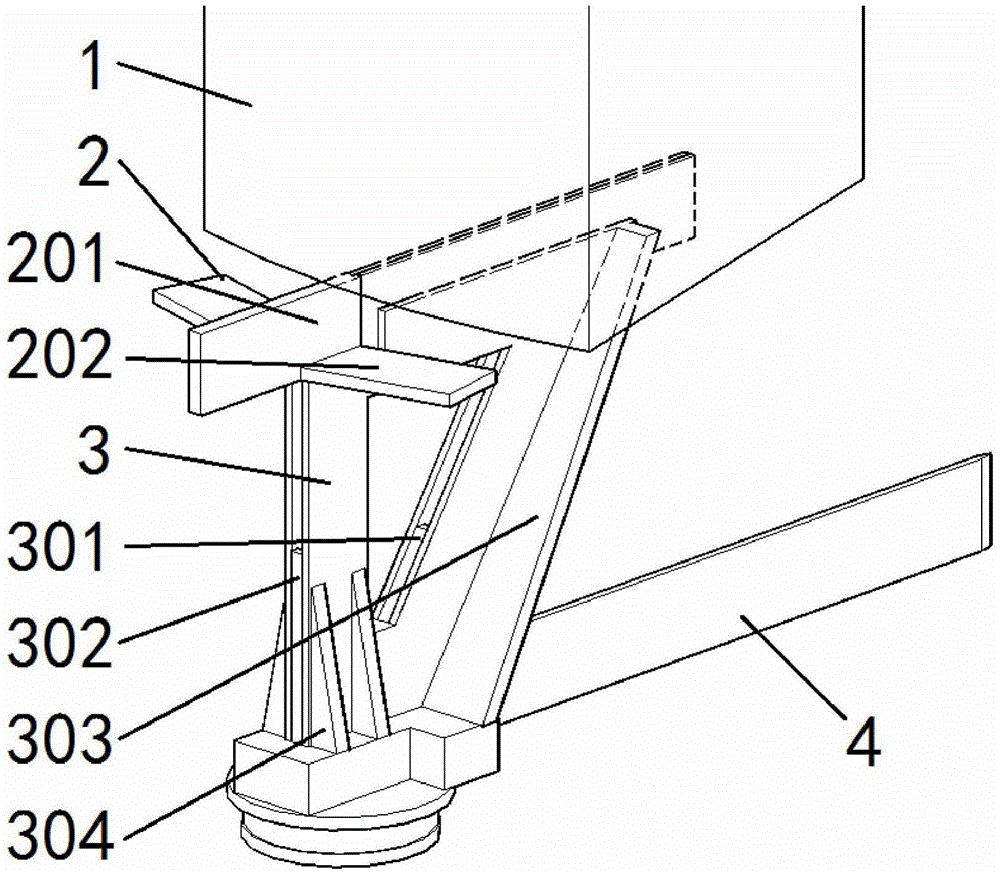
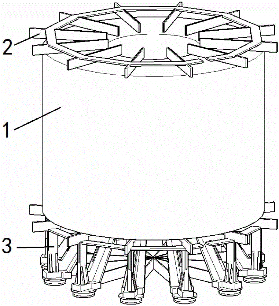
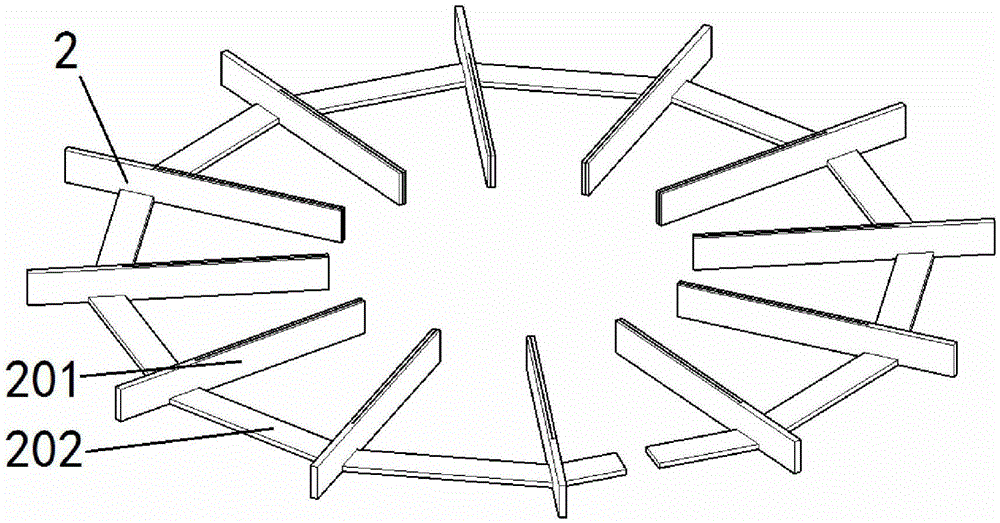
[0025] Such as Figure 1~3 As shown, the confluence and support structure of a dry-type reactor in the present invention includes a bus bar and a support frame. The bus bar 2 includes a vertical plate 201 and a connecting plate 202. The vertical plate is installed at the bottom of the reactor, and there are two connecting plates. Placed on both sides of the vertical plate, symmetrically arranged, multiple bus bars with the same above-mentioned structure are arrayed along the upper and lower parts of the dry-type reactor coil along the coil circumference, and the adjacent bus bar connecting plates are electrically connected in turn, leaving a non-electrical Connection position: the upper part of the supporting structure is provided with a notch, and the busbar installed at the lower part of the coil is installed in the notch of the supporting structure, and the supporting structure is arrayed along the circumference of the coil, corresponding to the busbar.

[0026] Such as i...


PUM


Abstract

The invention relates to a converging and supporting structure of a dry electric reactor. The converging and supporting structure comprises busbars and a supporting frame. Each busbar comprises a vertical plate and connecting plates. The vertical plates are mounted at the bottom of an electric reactor body, every two connecting plates are symmetrically arranged at the two sides of the corresponding vertical plate, the busbars with the same structure are arranged on the upper portion and the lower portion of a dry electric reactor coil along the circumference of the coil in an arrayed mode, the connecting plates of the adjacent busbars are electrically connected in sequence, and a non-electric connecting position is reserved in the circumferential direction. A notch is formed in the upper portion of the supporting structure, the busbars mounted on the lower portion of the coil are mounted in the notch of the supporting structure, and the supporting structure corresponds to the busbars along the circumference array of the coil. Due to the fact that an outer converging structure is adopted, the limit of the dry electric reactor to temperature rise can be met well, the running safety of the dry electric reactor is guaranteed, the failure rate of the dry electric reactor is lowered, the earthquake-resistant capacity is high, and local overheating is avoided.

Description

technical field [0001] The invention relates to a reactor manufacturing technology, in particular to a confluence and support structure of a dry-type reactor. Background technique [0002] At present, the confluence structure of dry-type reactors mainly adopts two sets of Mi-shaped structures (the Mi-shaped structure is connected to one point at the center and eight line segments radiate to the surroundings, and the Mi-shaped structure is not limited to eight line segments), which are respectively installed in the reactor coil. The upper and lower ends are electrically connected to the coil. The total current flows in through a certain branch of the Pozi-like shape, and is shunted to each branch of the Pozi-like shape through the center of the Pozi-shaped structure. The center of the Pozi-like structure is also the position where the magnetic flux leakage is relatively concentrated. As a result, the P-shaped center is prone to local overheating, which cannot meet the require...

Claims


Application Information

Patent Timeline
Patent Type & Authority Applications(China)
IPC IPC(8): H01F27/29H01F27/30
CPCH01F27/292H01F27/306
Inventor 党艳阳马嫱崔箫王恩龙
Owner TEBIAN ELECTRIC APP CO LTD
Why Eureka
Try Eureka