Conductive device

A conductive device and conductive bolt technology, applied in the field of robot welding, can solve the problems of contact surface wear, affecting the conductive effect, motor damage, etc., and achieve the effect of prolonging the service life

Inactive Publication Date: 2016-04-06
SUZHOU AOGUAN ROBOTIZATION EQUIP
View PDF7 Cites 4 Cited by
  • Summary
  • Abstract
  • Description
  • Claims
  • Application Information

AI Technical Summary

Problems solved by technology

However, during the welding process, the tooling needs to be continuously rotated. The conductive brush will wear the contact surface during the long-...

Method used


Image

  • Conductive device
  • Conductive device

Examples


Embodiment Construction

[0012] The present invention will be further described below in conjunction with the accompanying drawings.

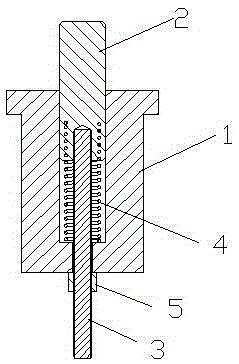
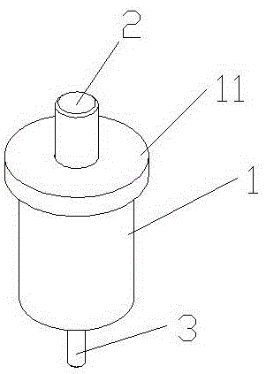
[0013] such as 1 and figure 2 As shown, a conductive device includes an insulating base 1 and a conductive connecting rod 3, the upper end of the insulating base 1 is provided with a first groove, and a conductive copper rod 2 is arranged in the groove, and the insulating base 1 The lower end of the conductive copper rod 2 is provided with an opening communicating with the groove, the center of the lower end of the conductive copper rod 2 is provided with a second groove along its axial direction, and one end of the conductive connecting rod 3 passes through the opening. The hole is in contact with the conductive copper rod 2 in the second groove, and a compression spring 4 is arranged on the conductive connecting rod 3 between the lower end of the conductive copper rod 2 and the bottom of the first groove.

[0014] The upward force is applied to the conductive coppe...


PUM


Abstract

The invention discloses a conductive device, which comprises an insulating base and a conductive connecting rod, wherein a first groove is formed in the upper end part of the insulating base; a conductive copper bar is arranged in the groove; an opening which is communicated with the groove is formed in the lower end part of the insulating base; a second groove is formed in the center position of the lower end part of the conductive copper bar along the axial direction; one end of the conductive connecting rod passes through the opening and enters the second groove to contact the conductive copper bar; and a compression spring is arranged on the conductive connecting rod between the lower end part of the conductive copper bar and the bottom part of the first groove. Acting force is applied to the conductive copper bar through the compression spring; the condition that the conductive copper bar is in contact with the lower surface of a tooling through elastic action even if the upper end surface of the conductive copper bar is abraded is ensured when the conductive copper bar is in contact with the tooling; and the service lifetime of the conductive device can be further prolonged by adjusting the penetration length of a conductive bolt under the condition of relatively large abrasion of the conductive copper bar.

Description

technical field [0001] The invention relates to a conductive device, which belongs to the technical field of robot welding. Background technique [0002] During the welding process of the robot, it is necessary to conduct electricity to the tooling. The existing conductive method usually uses a conventional conductive brush to contact the outer peripheral surface of the tooling to conduct electricity to it. However, during the welding process, the tooling needs to be continuously rotated. The conductive brush will wear the contact surface during the long-term friction process of the tooling. After a long period of wear, it will not only affect the conductive effect, but also easily cause damage to the motor. Contents of the invention [0003] The technical problem to be solved by the present invention is to provide a conductive device, which applies a force to the conductive copper rod through a compression spring to ensure that the conductive copper rod is in contact with...

Claims


Application Information

Patent Timeline
IPC IPC(8): H01R13/24H01R13/42H01R13/426
CPCH01R13/2421H01R13/2435H01R13/42H01R13/426
Inventor 洪峰李长星
Owner SUZHOU AOGUAN ROBOTIZATION EQUIP
Why Eureka
Try Eureka