Wire feeding device for multi-functional terminal machine

A multi-functional terminal and wire feeding device technology, which is applied in the direction of line/collector parts, electrical components, circuits, etc., can solve the problems of affecting the lead wire effect of the lead device and troublesome operation, so as to improve the speed of threading and the operation is simple and convenient , the effect of improving work efficiency

Inactive Publication Date: 2016-04-06
平湖市诚成电子科技有限公司
View PDF7 Cites 3 Cited by
  • Summary
  • Abstract
  • Description
  • Claims
  • Application Information

AI Technical Summary

Problems solved by technology

The wire feeding device of the existing terminal machine mainly includes a fixed plate fixed on the outside of the chassis. The fixed plate is provided with a number of guide wheels along the conveying direction of the electric wires. The guide wheels include slidable upper guide wheels and lower guide wheels, and wire clamps It is located between the upper guide wheel and the lower guide wheel. Through the cooperation of the upper guide wheel and the lower guide wheel, the wires can be pretreated before processing, and the wires are arranged in an orderly manner upstream of the front roller group, which is convenient for follow-up However, at present, the existing upper guide wheel is mainly fixed on the fixed plate through butterfly bolts, so that the distance between the upper guide wheel and the lower guide wheel is constant, and after wear and tear, the wires cannot Contact with the upper guide wheel or the lower guide wheel, which will affect the lead wire effect of the lead wire device. Moreover, if you want to adjust the distance between the upper guide wheel and the lower guide wheel, you need to loosen the butterfly bolts before you can adjust. Very troublesome to operate

Method used


Image

  • Wire feeding device for multi-functional terminal machine

Examples


Embodiment

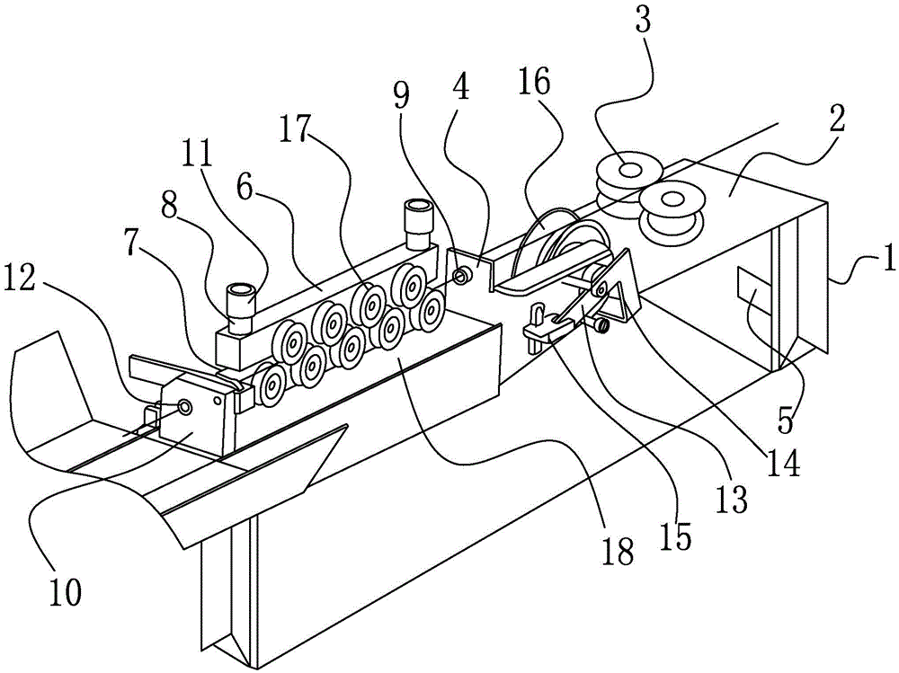
[0015] Example: such as figure 1 As shown, a wire feeding device for a multifunctional terminal machine includes a support frame 1, a wire feeding plate 2 and a correction plate 18 provided on the support frame 1, and a wire feeding wheel is arranged between the wire feeding plate 2 and the correction plate 18 device; the wire feeding plate 2 is provided with a pair of wire feeding wheels 3, a motor 5 that drives a pair of wire feeding wheels 3 to rotate relatively synchronously, the motor 5 is arranged on the support frame 1, and the wire feeding wheel device includes a guide plate 4, The driven wheel 16 and the adjusting device for adjusting the driven wheel 16, the guide plate 4 is provided with a guide pipe 9 corresponding to the center of the upper end of the driven wheel 16, and a pair of wire feed wheels 3 form a wire feeding channel , the wire feeding channel corresponds to the guide tube 9, the correction plate 18 is provided with a first adjustment plate 6 and a seco...


PUM


Abstract

The invention relates to a wire feeding device for a multi-functional terminal machine. The wire feeding device comprises a support frame (1), a wire feeding plate (2) and a correcting plate (18), wherein the wire feeding plate (2) is arranged on the support frame (1); a wire feeding wheel device is arranged between the wire feeding plate (2) and the correcting plate (18); the wire feeding plate (2) is provided with a pair of wire feeding wheels (3) and a motor (5); the motor (5) drives the pair of wire feeding wheels (3) to synchronously rotate oppositely; the motor (5) is arranged on the support frame (1); the wire feeding wheel device comprises a guide plate (4), a driven wheel (16) and an adjusting device; the adjusting device is used for adjusting the driven wheel (16); the guide plate (4) is provided with a guide pipe (9); and the guide pipe (9) corresponds to the center of the upper end of the driven wheel (16). Through coordination of the wire feeding wheel device and the wire feeding wheels, when an electric wire penetrates between the pair of wire feeding wheels, the driven wheel 16 and the wire feeding wheels can be always propped against the electric wire when working by adjusting the driven wheel 16, so that transmission of the electric wire can be relatively stably achieved.

Description

technical field [0001] The present invention relates to the technical field of a terminal machine, more specifically, it relates to a multifunctional terminal [0002] The wire feeding device of the machine. Background technique [0003] Terminal machine refers to a machine used in wire processing. It presses the metal head to the wire end and then conducts it. The wire feeding device of the existing terminal machine mainly includes a fixed plate fixed on the outside of the chassis. The fixed plate is provided with a number of guide wheels along the conveying direction of the electric wires. The guide wheels include slidable upper guide wheels and lower guide wheels, and wire clamps It is located between the upper guide wheel and the lower guide wheel. Through the cooperation of the upper guide wheel and the lower guide wheel, the wires can be pretreated before processing, and the wires are arranged in an orderly manner upstream of the front roller group, which is convenien...

Claims


Application Information

Patent Timeline
Patent Type & Authority Applications(China)
IPC IPC(8): H01R43/052
CPCH01R43/052
Inventor 刘秀中
Owner 平湖市诚成电子科技有限公司
Why Eureka
Try Eureka