Cable cooling apparatus

A cooling device and cable technology, applied in the direction of electrical components, etc., can solve the problems of power consumption, processing aging, ignition of contact objects, etc., achieve rapid cooling effect, rapid cooling and cooling, and prevent bending damage.

Active Publication Date: 2016-04-06
重庆伟刚电器成套设备有限公司
View PDF5 Cites 2 Cited by
  • Summary
  • Abstract
  • Description
  • Claims
  • Application Information

AI Technical Summary

Problems solved by technology

Especially for the cables routed inside the distribution box, due to the poor heat dissipation inside the distribution box, and the electrical components inside the distribution box are also dissipating heat, the superposition of these conditions will further aggravate the accumulation of heat , the accumulated heat poses a huge safety hazard to the power distribution workshop of the factory
Due to the small number of personnel and the large number of equipment in the power distribution workshop, long-term heat accumulation is likely to cause the softening of the cable sheath and the degree of processing aging, and it is easy to gradually ignite the contact object in the case of contact with other objects, causing a fire.
Some existing cooling devices are usually equipped with exhaust fans on the distribution box to dissipate the heat. However, this kind of device only discharges the heat into the workshop environment, and cannot reduce the overall temperature and risk of the workshop. Moreover, the distribution box Electrical components are usually dense in the electrical box, and in some areas where heat accumulates, the exhaust effect is not good. Therefore, it is difficult for this device to cool specific components.
In the prior art, there is also a device for adding a fan to a specific specific component, but this is only to discharge the heat of the specific component to other components, which is not conducive to overall cooling.
Moreover, the structure of the cable cooling device in the prior art is relatively complicated, the operability is not high, and additional power consumption is required

Method used


Image

  • Cable cooling apparatus

Examples


Embodiment Construction

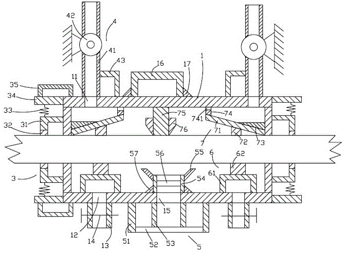
[0018] like figure 1 As shown in the figure, the cable cooling device of the present invention comprises a frame body 1, a fixing device 3 located on the left and right sides of the frame body 1, an air suction device 4 located above the frame body 1, and an inlet device located below the frame body 1. The air device 5 , the water tank device 6 located in the frame body 1 , and the air collecting device 7 located above the water tank device 6 .

[0019] like figure 1 As shown, the frame body 1 is a hollow cuboid, the frame body 1 is placed horizontally, and the frame body 1 is provided with first through holes 11 located on the left and right sides of the upper surface, and second through holes 11 located on the left and right sides of the lower surface. Two through holes 12 , a first pipe 13 located below the second through hole 12 , a first valve 14 disposed on the first pipe 13 , and a third through hole located between the second through holes 12 15. The holding frame 16...


PUM


Abstract

A cable cooling apparatus is disclosed. The cable cooling apparatus comprises a frame body, a fixing apparatus, a gas suction unit, an air inlet apparatus, a water tank apparatus and a gas collecting apparatus, wherein the frame body is provided with a first through hole, a second through hole, a first pipeline, a first valve, a third through hole, a grasping frame and a triangular block; the fixing apparatus comprises a first elastic sheet, a first friction block, a first spring, a first transverse rod and a first bracket; the gas suction unit comprises a second pipeline, a fan and a second bracket; the air inlet apparatus comprises a supporting ring, a first filter net, a third pipeline, a fourth pipeline, a fixing ring, a second filter net and a scattering hopper; the water tank apparatus comprises a water tank and a first fixing rod; the gas collecting apparatus comprises a gas collecting plate, a second fixing rod, a first fixing block, a connecting rod, a third fixing rod and a guide block; the first elastic sheet is L-shaped; and the first end of the first elastic sheet is fixedly connected with the side face of the frame body. The cable cooling apparatus can effectively cool cables, and is high in cooling speed and good in cooling effect without damaging the cables.

Description

technical field [0001] The invention relates to the technical field of cables, in particular to a cable cooling device. Background technique [0002] Large-scale electrical equipment in factories usually needs to be equipped with large distribution boxes. Since large-scale industrial production requires a large number of such distribution boxes, it is usually easy to operate under the action of long-term high current in the power distribution workshop of the factory. Heat buildup occurs. Especially for the cables routed inside the distribution box, since the heat dissipation inside the distribution box is not good, and the electrical components inside the distribution box are also dissipating heat, the superposition of these conditions further exacerbates the accumulation of heat. , the accumulated heat poses a huge safety hazard to the power distribution workshop of the factory. Due to the small number of personnel and more equipment in the power distribution workshop, lo...

Claims


Application Information

Patent Timeline
Patent Type & Authority Applications(China)
IPC IPC(8): H02G3/03
CPCH02G3/03
Inventor 金思思
Owner 重庆伟刚电器成套设备有限公司
Why Eureka
Try Eureka