Wireless power transmission device

A wireless charging and transmission device technology, applied in circuit devices, battery circuit devices, transmission systems, etc., can solve problems such as high energy and harm to the user's body, and achieve the effect of reducing energy, reducing damage, and improving wireless charging efficiency.

Inactive Publication Date: 2016-04-06
PRIMAX ELECTRONICS LTD
View PDF4 Cites 0 Cited by
  • Summary
  • Abstract
  • Description
  • Claims
  • Application Information

AI Technical Summary

Problems solved by technology

[0007] However, when the existing wireless charging transmission device 1 is in the detection mode and the existing electronic device 2 is not placed on the main body 10, since there is no object on the main body 10 to absorb the magnetic flux generated by the electromagnetic effect, and due to the short-term The generated energy is too large, causing the electromagnetic waves to scatter around in the form of radiation. In addition to affecting other electronic devices, the scattered electromagnetic waves may also harm the user's body

Method used


Image

  • Wireless power transmission device
  • Wireless power transmission device
  • Wireless power transmission device

Examples


Embodiment Construction

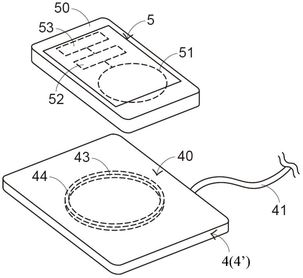
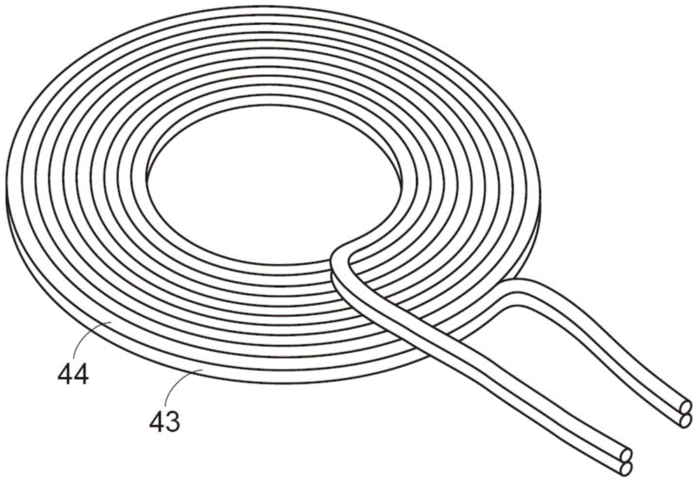
[0030] In view of the problems caused by the prior art, the present invention provides a wireless charging transmission device. Please also see figure 2 , image 3 as well as Figure 4 , figure 2 It is a schematic structural diagram of the wireless charging transmission device and the electronic device in the first preferred embodiment of the present invention, and image 3 It is a schematic structural diagram of the first transmission coil and the second transmission coil of the wireless charging transmission device of the present invention in the first preferred embodiment, and Figure 4 It is a schematic block diagram of the first transmission coil and the second transmission coil of the wireless charging transmission device of the present invention in the detection mode in the first preferred embodiment. figure 2 A wireless charging transmission device 4 and an electronic device 5 are shown, and the wireless charging transmission device 4 includes a body 40, a power...


PUM


Abstract

The present invention relates to a wireless power transmission device for wirelessly charging an electronic device. The wireless power transmission device includes a main body, a driving circuit, a first transmitter coil and a second transmitter coil. The second transmitter coil is stacked over the first transmitter coil. If the wireless power transmission device is operated in a detecting mode, the driving circuit periodically provides the first voltage to the first transmitter coil at a first predetermined time interval, so that a magnetic flux is generated by the first transmitter coil and oriented in the direction toward the top surface of the main body. The magnetic flux is attenuated by the overlying second transmitter coil. Consequently, the electromagnetic wave is inhibited. If the wireless power transmission device is operated in a charging mode, the driving circuit provides the second voltage to the first transmitter coil and the second first transmitter coil, and both the first transmitter coil and the second transmitter coil are controlled to generate and transmit magnetic fluxes. Since the intensity of the electric power is increased, the charging efficiency is enhanced.

Description

technical field [0001] The present invention relates to a charging transmission device, in particular to a wireless charging transmission device utilizing wireless charging technology. Background technique [0002] Various electronic devices must be connected to a power supply to obtain power before they can be used. Generally speaking, electronic devices are plugged into a power source (such as a power socket) by a power cord to obtain power. With the development of science and technology, various electronic devices have become thinner and lighter in response to the needs of users, so as to be easy to carry. Due to the portable nature of the electronic device, the electronic device cannot rely on the power line to obtain power at any time. Therefore, a rechargeable battery must be provided in the electronic device to provide power to the electronic device. [0003] When the power of the rechargeable battery in the electronic device is insufficient, the user uses a chargin...

Claims


Application Information

Patent Timeline
Patent Type & Authority Applications(China)
IPC IPC(8): H02J17/00
CPCH02J50/10H02J7/00712H02J50/005H04B5/79
Inventor 何永先丘宏伟罗骏豪
Owner PRIMAX ELECTRONICS LTD
Why Eureka
Try Eureka