Rotor iron core and motor equipped with same

A technology of rotor core and iron core, which is applied in the field of rotor core and motors with it, can solve the problems that the magnetic flux leakage of the connecting bridge cannot be reduced again, the rotor core is broken, and the performance and efficiency of the motor are affected, and the equipment can be improved. Performance, reduction of magnetic flux leakage, effect of reduction of magnetic flux leakage

Active Publication Date: 2016-04-06
GREE ELECTRIC APPLIANCES INC +1
View PDF6 Cites 11 Cited by
  • Summary
  • Abstract
  • Description
  • Claims
  • Application Information

AI Technical Summary

Problems solved by technology

However, when the speed of the high-speed motor reaches 10,000 to 20,000 rpm, the high-speed centrifugal force generated by the rotor core and the magnetic steel will cause the weak edge of the rotor core (between magnetic poles) to break
Moreover, there is a rotor core part between the magnetic poles, that is, the connecting bridge, and the magnetic flux leakage of the connecting bridge cannot be reduced again, which affects the performance and efficiency of the motor.

Method used


Image

  • Rotor iron core and motor equipped with same
  • Rotor iron core and motor equipped with same
  • Rotor iron core and motor equipped with same

Examples


Embodiment Construction

[0025] It should be noted that, in the case of no conflict, the embodiments in the present application and the features in the embodiments can be combined with each other. The present invention will be described in detail below with reference to the accompanying drawings and examples.

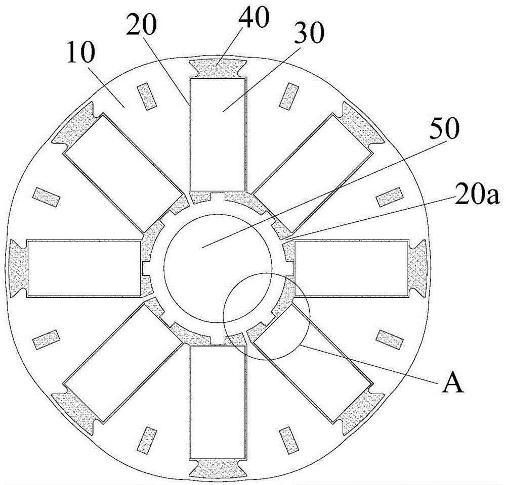
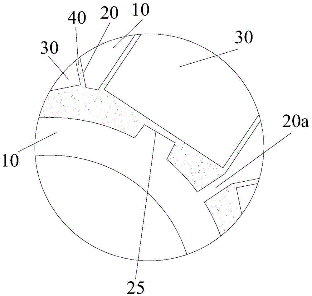
[0026] Such as figure 2 and image 3 As shown, the present invention provides a rotor core.

[0027] Specifically, the rotor core includes a core body 10 , a plurality of magnetic steel slots 20 and a plurality of magnetic steels 30 . Wherein, a plurality of magnetic steel slots 20 are opened on the iron core body 10, and a plurality of magnetic steel slots 20 are arranged at intervals along the circumferential direction of the iron core body 10, and each magnetic steel slot 20 extends along the radial direction of the iron core body 10 . The magnetic steel slot 20 has a first end close to the center of the rotor iron core and a second end far away from the center of the rotor iron core, t...


PUM


Abstract

The invention provides a rotor iron core and a motor equipped with the same. The rotor iron core comprises an iron core body, multiple magnetic steel grooves and multiple magnetic steels, wherein the multiple magnetic steel grooves are formed in the iron core body and are formed at intervals along the circumferential direction of the iron core body; each magnetic steel groove extends in a radial direction of the iron core body; each magnetic steel groove is provided with a first end close to the rotor iron core center and a second end far from the rotor iron core center; the multiple magnetic steels are arranged in the multiple magnetic steel grooves in a one-to-one correspondence manner, wherein the first ends of a part of the multiple magnetic steel grooves are spaced at intervals to form connecting bridges while the first ends of the other magnetic steel grooves are connected. Magnetic field flux leakage occurs from the connecting bridges; according to the technical scheme of the rotor iron core and the motor equipped with the same, the first ends of a part of the multiple magnetic steel grooves are connected but not spaced at intervals to form the connecting bridges, so that the number of the connecting bridges among the magnetic steels is reduced, and the flux leakage phenomenon is reduced as well; and therefore, the rotor iron core and the motor equipped with the same can reduce flux leakage and improve the equipment performance.

Description

technical field [0001] The invention relates to power equipment, in particular to a rotor iron core and a motor with the same. Background technique [0002] Such as figure 1 As shown, the conventional tangential rotor structure includes a core body 10', a magnetic steel groove 20' and a magnetic steel 30'. In order to reduce magnetic flux leakage, it is usually necessary to reduce the width between magnetic poles as much as possible to achieve the effect of limiting magnetic flux leakage. However, the thinner the width between the magnetic poles, the smaller the magnetic flux leakage between the magnetic poles, and the higher the magnetic flux per pole, which can increase the power density of the motor. However, when the speed of a high-speed motor reaches 10,000 to 20,000 revolutions, the high-speed centrifugal force generated by its rotor core and magnetic steel will cause the weak edge of the rotor core (between magnetic poles) to break. Moreover, there is a rotor iron...

Claims


Application Information

Patent Timeline
Patent Type & Authority Applications(China)
IPC IPC(8): H02K1/27
Inventor 胡余生钟成堡焦雷王庆凯许金鑫谢芳
Owner GREE ELECTRIC APPLIANCES INC
Why Eureka
Try Eureka