A rotary linear permanent magnet motor

A permanent magnet motor and linear electric technology, applied to synchronous motors with stationary armatures and rotating magnets, electrical components, electromechanical devices, etc., can solve the problems of inconvenient control, inability to control independently, increase equipment volume and weight, etc. To achieve the effect of solving low efficiency and improving accuracy and efficiency

Active Publication Date: 2018-07-06
NINGBO INST OF MATERIALS TECH & ENG CHINESE ACADEMY OF SCI
View PDF6 Cites 2 Cited by
  • Summary
  • Abstract
  • Description
  • Claims
  • Application Information

AI Technical Summary

Problems solved by technology

Usually, this kind of multi-degree-of-freedom motion is realized by mechanical splicing and combination of basic elements that can perform linear or rotational motion, but this method has the following problems: First, because there are mechanical elements in its functional parts, Its friction, wear and deformation are relatively serious; second, the rotary motion and linear motion are coupled and cannot be controlled independently; third, the accuracy of this actuator is limited by machining; fourth, the use of multiple motors to control Not only will it increase the size and weight of the device, but it will also bring inconvenience to the control
PCT patent WO2008 / 096519 A1 discloses a rotary linear motor. The stator of this motor has two sets of windings, namely the rotary armature winding and the linear armature winding. The polarity is the same in the direction of rotation and axial line, and opposite to the polarity in the direction of oblique angle, but the installation of permanent magnets in this structure is complicated

Method used


Image

  • A rotary linear permanent magnet motor
  • A rotary linear permanent magnet motor
  • A rotary linear permanent magnet motor

Examples


Embodiment Construction

[0025] In order to make the object, technical solution and advantages of the present invention clearer, the rotary linear permanent magnet motor of the present invention will be further described in detail below in conjunction with the accompanying drawings and embodiments. It should be understood that the specific embodiments described here are only used to explain the present invention, not to limit the present invention.

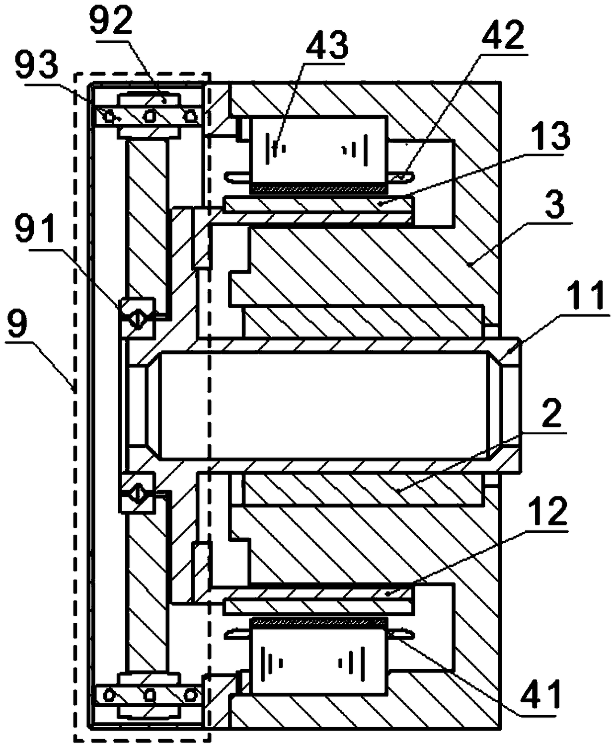
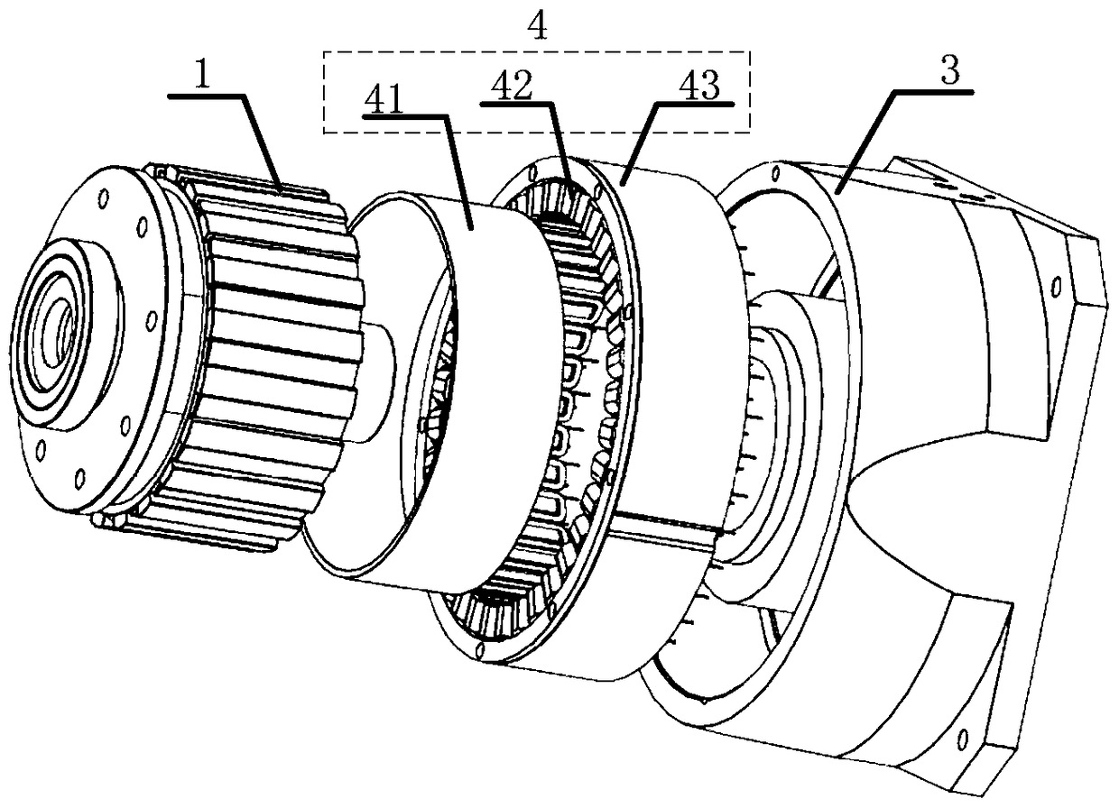
[0026] refer to Figure 1 to Figure 5 , a rotary linear permanent magnet motor according to an embodiment of the present invention includes a rotor 1 , an air bearing 2 , a support seat 3 , a stator 4 , a mechanical decoupling device 9 and an inner rotor shaft 11 . The main body of the support seat 3 is a circular groove, and an annular protrusion is arranged in the circular groove. An annular accommodation space is formed between the annular protrusion and the side wall of the annular groove. Both the stator 4 and the rotor 1 are placed on the support se...


PUM


Abstract

The invention provides a rotary linear permanent magnet motor, which includes a stator, a rotor and a mechanical decoupling device; the stator and the rotor are placed in a support seat, the stator includes a stator core, a rotating armature winding and a linear armature winding; the rotor includes a rotor iron core and the permanent magnet of the rotor; the mechanical decoupling device includes a rotary bearing, a sliding bracket and a sliding guide rail; the sliding bracket is connected to the inner shaft of the rotor through the rotating bearing, the sliding bracket is arranged on the sliding guide rail, and the sliding bracket can be positioned relative to the sliding guide rail on the axis of the inner shaft of the rotor within the axial length of the stator core, the radial direction of the rotary linear permanent magnet motor from the inside to the outside is the rotor inner shaft, the air bearing, the annular protrusion of the support seat, the rotor core, the rotor permanent Magnets, linear armature windings, rotating armature windings and stator cores. The rotary linear permanent magnet motor of the present invention realizes the multi-degree-of-freedom movement of a single motor, and improves the precision and efficiency of motor operation.

Description

technical field [0001] The invention relates to the field of motors, in particular to a rotary linear permanent magnet motor. Background technique [0002] Traditional motors generally can only provide single-degree-of-freedom motion (rotary motion or linear motion), but cannot realize compound motion of rotation and linear motion. However, in systems such as robotic joints, industrial production, processing, and assembly, it is often necessary to achieve multi-freedom motion. Usually, this kind of multi-degree-of-freedom motion is realized by mechanical splicing and combination of basic elements that can perform linear or rotational motion, but this method has the following problems: First, because there are mechanical elements in its functional parts, Its friction, wear and deformation are relatively serious; second, the rotary motion and linear motion are coupled and cannot be controlled independently; third, the accuracy of this actuator is limited by machining; fourth,...

Claims


Application Information

Patent Timeline
Patent Type & Authority Patents(China)
IPC IPC(8): H02K21/14H02K41/03H02K41/00
Inventor 陈进华廖有用张驰孙鹏
Owner NINGBO INST OF MATERIALS TECH & ENG CHINESE ACADEMY OF SCI
Why Eureka
Try Eureka