Communication device for motor vehicle
A technology for communication devices and motor vehicles, applied in the field of antenna circuits, can solve the problems that the frequency response of the carrier frequency varies greatly, the order of magnitude is equal to the antenna current, and the result is not as expected.
- Summary
- Abstract
- Description
- Claims
- Application Information
AI Technical Summary
Problems solved by technology
Method used
Image
Examples
Embodiment Construction
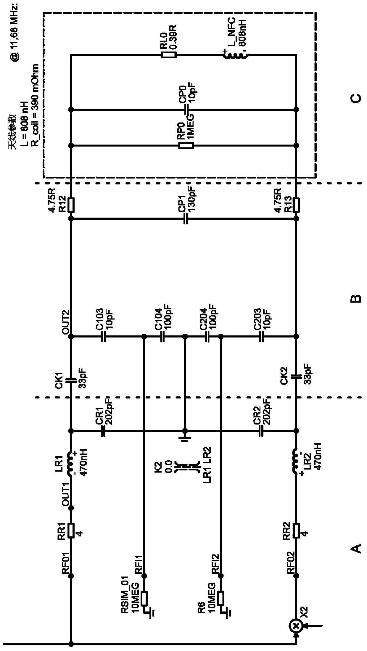
[0033] exist Figure 1a A schematic diagram of a circuit simulation for driving an NFC antenna is shown in . Part A represents the power grid for EMV filtering, part B represents the impedance matching circuit, and part C is the equivalent circuit diagram of the antenna array. In this example, the antenna parameters are 808 nH at a frequency of 11.68 MHz and its coil resistance is 390 mOhm.
[0034] The circuit shown is optimized according to the driver circuit manufacturer's requirements, first considering the antenna (C) and its measured performance, followed by the impedance matching device (B), and finally the filtering device (A) and finally the optimized device.
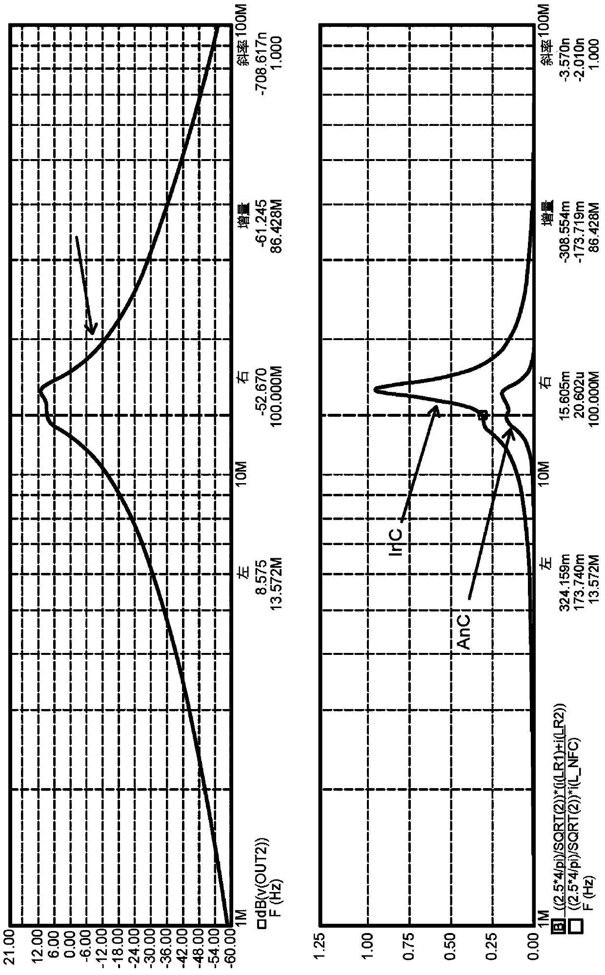
[0035] exist Figure 1b shown in the upper part of the Figure 1a Filter curve for the circuit shown. exist Figure 1b The frequency responses of the antenna current (AnC) and the input current (InC) are shown in the lower part of .
[0036] It is clearly seen that in this example the input current is above...
PUM
 Abstract
Description
Claims
Application Information
 - R&D
- Intellectual Property
- Life Sciences
- Materials
- Tech Scout
- Unparalleled Data Quality
- Higher Quality Content
- 60% Fewer Hallucinations
Browse by: Latest US Patents, China's latest patents, Technical Efficacy Thesaurus, Application Domain, Technology Topic, Popular Technical Reports.
© 2025 PatSnap. All rights reserved.Legal|Privacy policy|Modern Slavery Act Transparency Statement|Sitemap|About US| Contact US: help@patsnap.com


