Radiation spurious emission (RSE) auxiliary test circuit

A technology for auxiliary testing and detection circuits, applied in the field of circuits, which can solve problems such as impedance mismatch and non-compliance with standards

Inactive Publication Date: 2016-04-06
SHENZHEN FUTAIHONG PRECISION IND CO LTD +1
View PDF0 Cites 8 Cited by
  • Summary
  • Abstract
  • Description
  • Claims
  • Application Information

AI Technical Summary

Problems solved by technology

At present, in the EMC test, the comprehensive tester is connected to the RF switch during the CSE test, and the impedance matching can be realized by changing the load at the output end of the power amplifier, and the CSE tes

Method used


Image

  • Radiation spurious emission (RSE) auxiliary test circuit
  • Radiation spurious emission (RSE) auxiliary test circuit

Examples


Embodiment Construction

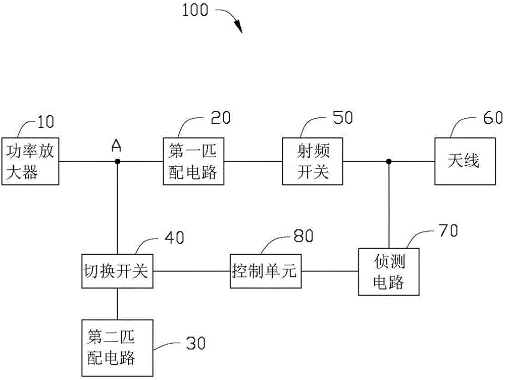
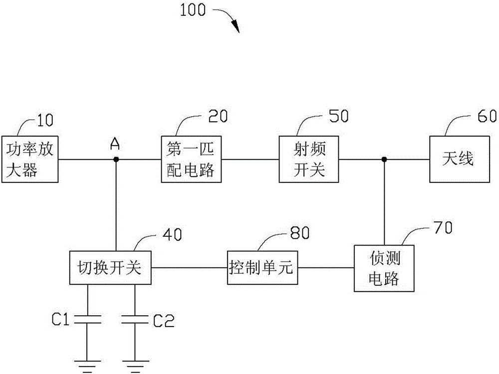
[0011] see figure 1 A preferred embodiment of the present invention provides a radiation spurious auxiliary test circuit 100, which is applied to an electronic device. The radiation spurious auxiliary test circuit 100 includes a power amplifier 10, a first matching circuit 20, a second matching circuit 30, A switch 40 , a radio frequency switch 50 , an antenna 60 , a detection circuit 70 and a control unit 80 .

[0012] The power amplifier 10 is used to amplify the signal of the specified frequency band, and also generate some frequency components outside the specified frequency band, wherein the frequency component is an integer multiple of the specified frequency band called harmonics, and the amplitude of the harmonics is generally large. 60 will cause interference to other devices.

[0013] The first matching circuit 20 is electrically connected between the power amplifier 10 and the radio frequency switch 50 for achieving impedance matching between the power amplifier 10...


PUM


Abstract

The invention provides a radiation spurious emission (RSE) auxiliary test circuit which is applied to an electronic device. The auxiliary test circuit comprises a power amplifier, a first match circuit, a radio frequency switch, an antenna, a second match circuit, a change-over switch, a detecting circuit and a control unit, which are connected electrically in sequence. The second match circuit is electrically connected to the change-over switch; the change-over switch is electrically connected to a node between the power amplifier and the first match circuit; the detecting circuit is electrically connected between the radio frequency switch and the antenna; the control unit is electrically connected between the change-over switch and the detecting circuit; the detecting circuit is used for judging whether the electronic device is subjected to the RSE test and outputting the corresponding detecting result; and the control unit controls the change-over switch to establish or disconnect the electrical connection between the second match circuit and the node according to the detecting result, so that when the electronic device is subjected to the RSE test, the power amplifier and the antenna reach impedance matching therebetween.

Description

technical field [0001] The invention relates to a circuit, in particular to a radiation spurious auxiliary test circuit. Background technique [0002] In the production process, mobile phones need to pass a series of detections before they can be launched into the market. One of the important detections is the ElectroMagnetic Compatibility (EMC) test, and the EMC detection includes Conductive Spurious Emissions, CSE) test and radiation spurious (RadiationSpuriousEmissions, RSE) test. At present, in the EMC test, the comprehensive tester is connected to the RF switch during the CSE test, and the impedance matching can be realized by changing the load at the output end of the power amplifier, and the CSE test is qualified, while the RF switch is connected to the antenna during the RSE test, changing the impedance, making the If the impedance does not match, the RSE test does not meet the standard, so how to improve the RSE test is an important issue. Contents of the inventi...

Claims


Application Information

Patent Timeline
IPC IPC(8): H04M1/24G01R31/00
Inventor 王晓冬沙坚
Owner SHENZHEN FUTAIHONG PRECISION IND CO LTD
Why Eureka
Try Eureka