Antisuction device for high speed turbine toothdrill handpiece

A dental drill handpiece and anti-suckback technology, which is applied in dental drilling, dentistry, orthodontics, etc., to achieve the effects of enhancing wear resistance, reducing wear, and increasing braking sensitivity

Active Publication Date: 2016-04-13
BEIJING DONGBO PNEUMATIC TOOL CO LTD
View PDF6 Cites 15 Cited by
  • Summary
  • Abstract
  • Description
  • Claims
  • Application Information

AI Technical Summary

Problems solved by technology

[0008] The purpose of the present invention is to solve the problem of iatrogenic cross-infection caused by the unavoidable back-suction of the conventional high-speed turbine dental handpiece, and can greatly prolong the service life of the bearing

Method used


Image

  • Antisuction device for high speed turbine toothdrill handpiece
  • Antisuction device for high speed turbine toothdrill handpiece
  • Antisuction device for high speed turbine toothdrill handpiece

Examples


Embodiment 1

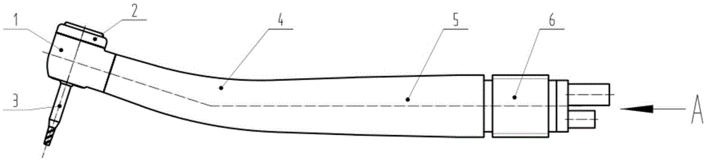
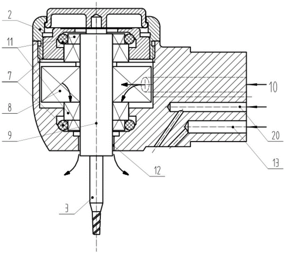
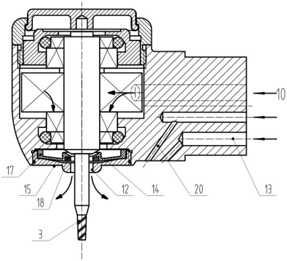
[0043] see figure 1 , image 3 , Figure 4 , Figure 5 . The present invention comprises machine head body 1, machine head cover 2, drill needle 3, front machine handle 4, rear machine handle 5, air-water joint 6. The anti-back suction device of the present invention is installed on the end face 14 where the wind wheel shaft 9 of the high-speed turbine dental drill handpiece is installed with the drill needle 3 . The compressed air from the dental treatment machine passes into the handpiece body 1 through the air-water joint 6 of the rear machine handle 5 and can blow the wind wheel 8 to rotate. The axial component of the compressed airflow blowing the wind wheel can flow to the sealing place between the conical brake surface 14 of the wind wheel shaft and the central cone surface 19 of the shaft seal cover through the gap 12 of the wind wheel shaft and the machine head body. At the same time, the elastic shaft seal cover 17 can be inflated, and the inflated elastic shaft...

Embodiment 2

[0049] The high-speed turbo dental drill handpiece equipped with the anti-suckback device has no difference in use and operation from other turbo dental drill handpieces.

[0050] The universal interface of the mobile phone of the dental treatment machine is connected with the air-water joint of the rear machine handle of the mobile phone of the present invention. It is used to transmit the compressed air for driving the wind wheel and the pressure water for cooling the drill bit. When the doctor turns on the foot switch, compressed air and pressurized water flow into the head body. The compressed air drives the wind wheel and the drill bit to rotate from the air inlet 10, and the other air flow channel 20 and the pressure water channel 13 jointly form water mist for cooling the drill bit. At this time, the axial component airflow of the compressed air driving the wind wheel will inflate the elastic shaft seal cover 17 and press against the inner wall of the shaft cover 15. A...


PUM


Abstract

The invention relates to an antisuction device for a high speed turbine toothdrill handpiece. The antisuction device is mounted on one side, where the drill point is arranged, of the handpiece body; the antisuction device further comprises an elastic shaft seal cover, a non-elastic shaft seal cover and a metal ring, wherein the elastic shaft seal cover, the non-elastic shaft seal cover and the metal ring are sequentially connected, at the moment the toothdrill handpiece stalls, the elastic shaft seal cover is pressed towards the cone-shaped braking surface of a rotor shaft, so that prompt braking is realized, and antisuction is prevented; as the metal ring in the center of the elastic shaft seal cover is inflexible and higher in inner hole precision, the defect that the circulation area is decreased due to arc deformation of the elastic shaft seal cover after being inflated is overcome, the rotating speed and the output power losses are reduced, and the non-elastic shaft seal cover can prevent the elastic shaft seal cover from losing the elasticity due to excessive inflation; when braking is carried out, as the rotating speed of the rotor is quite low, the service life of the elastic shaft seal cover can be prolonged by adopting an elastic material with better abrasive resistance; besides, the antisuction device can effectively prevent antisuction to prevent tooth particles and liquid in the oral cavity from entering the toothdrill handpiece, so that the service life of the bearing in the toothdrill handpiece can be greatly prolonged.

Description

technical field [0001] The invention belongs to a medical device, in particular to a dental hand-held appliance for drilling and grinding teeth. Background technique [0002] The existing high-speed turbine dental drill handpiece comprises a head body, a head cover, a drill needle, a front handle, a rear handle, and an air-water joint. It is connected with the dental treatment machine to obtain the compressed air and cooling pressure water for the mobile phone to work. The front handle is the part held by the doctor. A wind wheel that can be driven by compressed air is installed in the machine head body. The wind wheel is installed in the middle of the wind wheel shaft, supported by two bearings and damped by two O-shaped rubber rings. Two disadvantages of the present dental drill handpiece are suckback phenomenon and low bearing life, and suckback phenomenon is the main cause of iatrogenic cross-infection and low bearing life. [0003] 1) Generation of pollution sources ...

Claims


Application Information

Patent Timeline
Patent Type & Authority Applications(China)
IPC IPC(8): A61C1/05
CPCA61C1/057
Inventor 张福东
Owner BEIJING DONGBO PNEUMATIC TOOL CO LTD
Why Eureka
Try Eureka