Engine cylinder upper stop point positioning device and positioning method

An engine cylinder and positioning device technology, which is applied to workpiece clamping devices, manufacturing tools, etc., can solve the problems of difficulty in measuring multi-cylinder engines, complex structure, high cost, low positioning efficiency, etc., and achieves convenient measurement of multi-cylinder engines and simple structure. Low cost and high positioning efficiency

Inactive Publication Date: 2016-04-13
ZHEJIANG GEELY POWERTRAIN CO LTD
View PDF7 Cites 0 Cited by
  • Summary
  • Abstract
  • Description
  • Claims
  • Application Information

AI Technical Summary

Problems solved by technology

[0003] The purpose of the present invention is to overcome the disadvantages of the current top dead center measurement device for engine cylinders, such as difficulty in measuring multi-cylinder engines, complex structure, high cost, and low positioning efficiency, and to provide a method for measuring multi-cylinder engines that is convenient, simple in structure, low in cost, and capable of positioning Higher efficiency engine cylinder top dead center positioning device and positioning method

Method used


Image

  • Engine cylinder upper stop point positioning device and positioning method
  • Engine cylinder upper stop point positioning device and positioning method

Examples


Embodiment Construction

[0015] The present invention will be further described below in conjunction with the accompanying drawings.

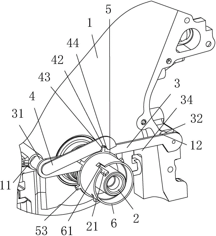
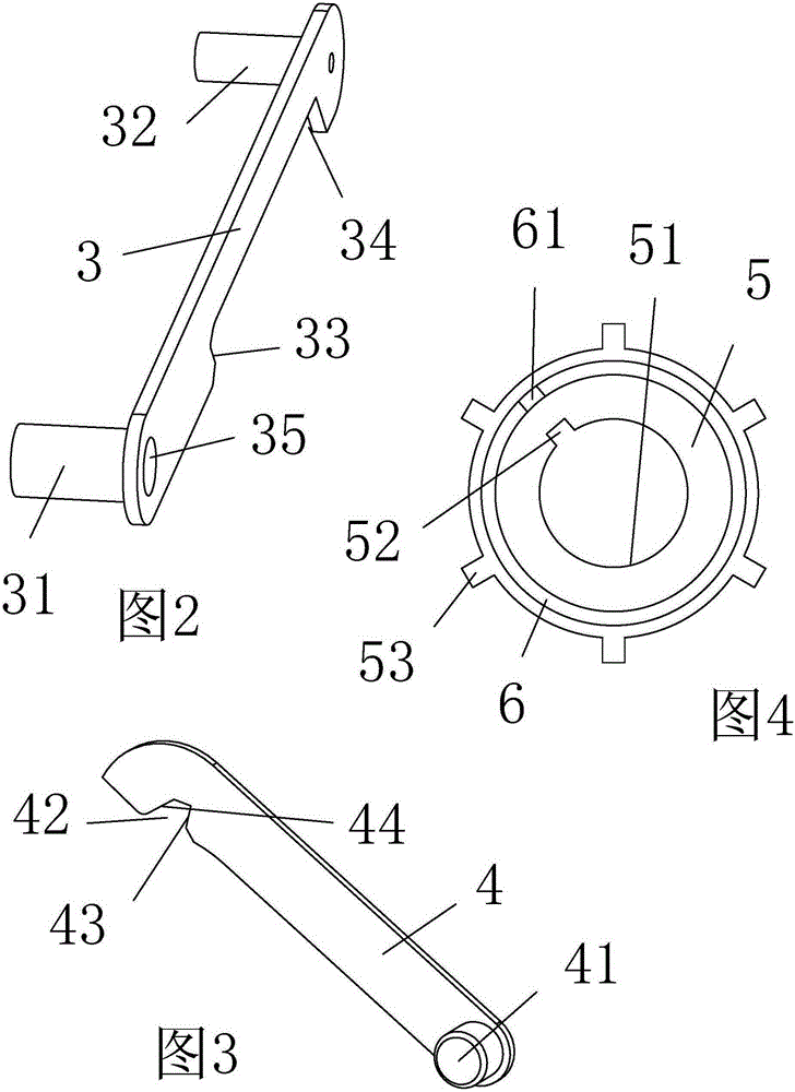
[0016] as attached figure 1 to attach Figure 4 Shown: a positioning device for the top dead center of an engine cylinder, including a cylinder block 1 of an engine with a first positioning hole 11 and a second positioning hole 12 at one end, and a crankshaft with a connecting key 21 at one end and protruding from one end of the cylinder block 1 2. One side is provided with the positioning rod 3 of the first positioning shaft 31 which is in clearance fit with the first positioning hole 11 and the second positioning shaft 32 is in clearance fit with the second positioning hole 12, and one end is provided with the other side of the positioning rod 3 A hinged shaft 41 hinged at one end and a one-way thrust rod 4 whose rotation axis is parallel to the axis of the crankshaft 2 of the engine is provided with an inner hole 51 that is loosely fitted with the crankshaft 2 and ...


PUM


Abstract

The invention relates to the field of manufacturing of vehicle engine cylinders, and aims to provide an engine cylinder upper stop point positioning device and a positioning method. The engine cylinder upper stop point positioning device comprises a cylinder body of an engine provided with a first positioning hole and a second positioning hole, a crankshaft provided with a connecting key, a positioning rod provided with a first positioning shaft and a second positioning shaft, a one-way thrust rod provided with a hinge shaft hinged to the positioning rod, an indexing plate provided with an inner hole and a key slot, a rocking handle connecting pipe connected with the indexing plate, multiple indexing teeth uniformly arranged at the outer side periphery of the indexing plate, an initial positioning recess provided with an initial positioning surface at the lower end of the positioning rod, and a back positioning recess provided with a back positioning surface and a guide inclined surface at the lower end of the one-way thrust rod. The engine cylinder upper stop point positioning device is convenient to measure a multi-cylinder engine, and is simple in structure, low in cost and higher in positioning efficiency. The positioning method of the engine cylinder upper stop point positioning device can satisfy sequential determination of upper stop points of all cylinders of the engine, and is higher in positioning efficiency.

Description

technical field [0001] The invention relates to the field of automobile engine cylinder manufacturing, in particular to a top dead center positioning device and a positioning method for an engine cylinder. Background technique [0002] Assembling the automobile engine, adjusting the valve clearance and adjusting the timing all need to locate the top dead center of each cylinder; the utility model of Chinese patent application number: 201220501420.4 discloses a measuring device for the top dead center of the engine cylinder, which includes a fixed seat, a scale And the ejector rod, the fixed seat is used to fix the measuring device to the cylinder head, the scale has a scale, the ejector rod is horizontally fixed on the top of the scale, and the ejector rod can be fixed on the top of the valve stem to follow the valve up and down sports. The engine cylinder top dead center measurement device has the disadvantage of measuring multi-cylinder engines; the invention of Chinese p...

Claims


Application Information

Patent Timeline
IPC IPC(8): B25B11/00
CPCB25B11/00
Inventor 万法高陈政弘王瑞平
Owner ZHEJIANG GEELY POWERTRAIN CO LTD
Why Eureka
Try Eureka