
Automatic grabbing manipulator capable of adapting to motor rotors with different diameters

A technology for grasping manipulators and motor rotors, applied in metal processing and other directions, can solve the problems of labor shortage, short processing time, low processing efficiency, etc., and achieve the effects of high efficiency, simple structure, low cost, and labor cost saving.

Inactive Publication Date: 2015-11-18
SUZHOU SANTI INTELLIGENT TECH
View PDF9 Cites 10 Cited by
  • Summary
  • Abstract
  • Description
  • Claims
  • Application Information

AI Technical Summary

Problems solved by technology

At present, there are mainly the following limitations in the processing of motor rotors: (1) Low degree of automation and low processing efficiency
Although there are equipment for automatic loading and unloading and clamping on the market, most of the equipment uses manipulators to realize the loading, unloading and clamping of motor rotors. Too long clamping time seriously affects the processing efficiency of motor rotors, and the cost of manipulators is relatively high. Therefore, most of the loading and unloading and clamping of the motor rotor are done manually, resulting in a low degree of automation and low efficiency in the processing process.
(2) The labor intensity of workers is high and there are potential safety hazards
During the processing of the motor rotor, due to the short processing time, workers need to manually load and unload and clamp frequently, and directly contact the machine tool, which is labor intensive and poses serious safety hazards during long-term work.
(3) Difficulty in recruitment and labor shortage

Method used


Image

  • Automatic grabbing manipulator capable of adapting to motor rotors with different diameters
  • Automatic grabbing manipulator capable of adapting to motor rotors with different diameters
  • Automatic grabbing manipulator capable of adapting to motor rotors with different diameters

Examples


Embodiment Construction

[0017] The present invention will be further described below in conjunction with the accompanying drawings.

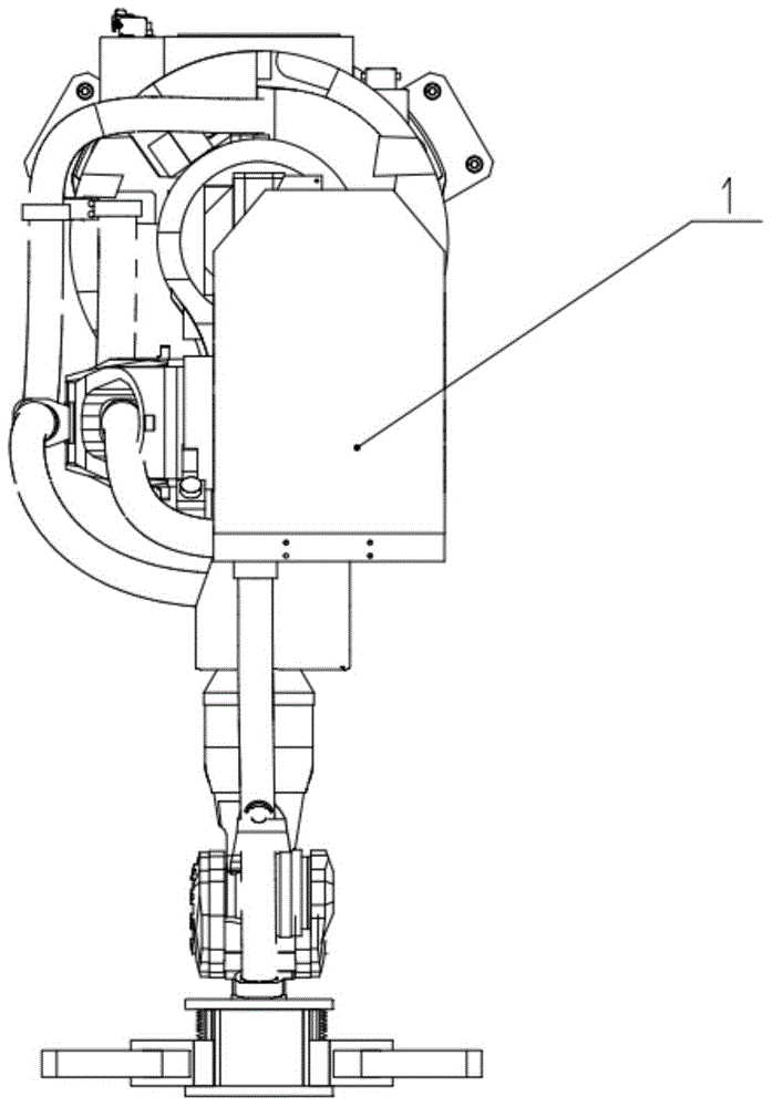
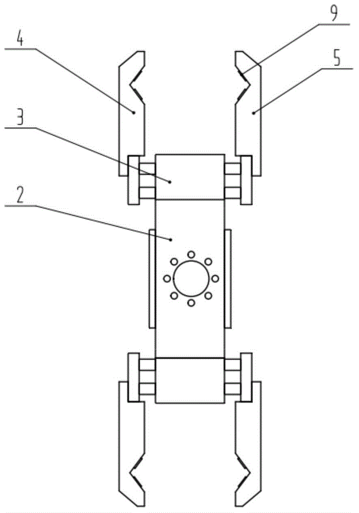
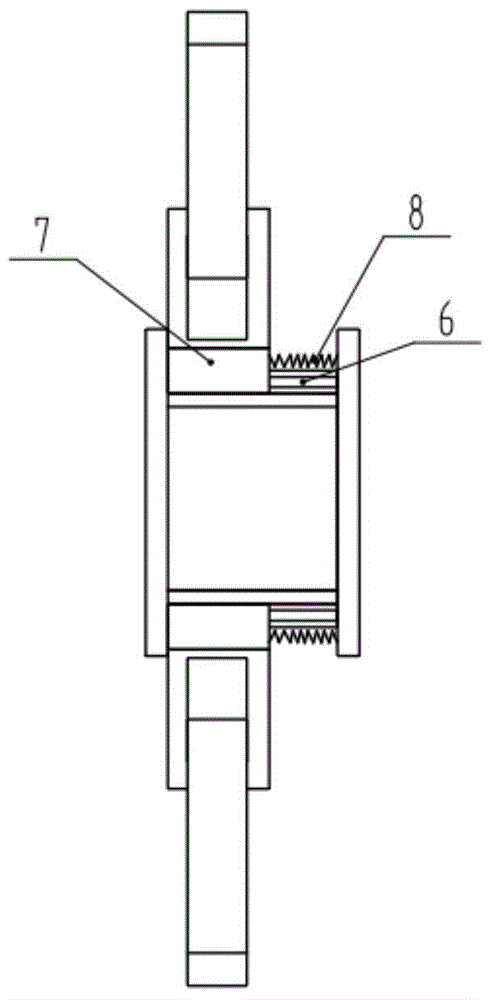
[0018] as attached figure 1 to attach image 3 An automatic grasping manipulator that can adapt to motor rotors with different diameters is shown, including an industrial robot 1, a cylinder frame 2, a parallel cylinder 3, a first grasping finger 4 and a second grasping finger 5, and the cylinder frame 2 is equipped with Two parallel cylinders 3, all parallel cylinders 3 are evenly distributed and installed relative to the rotation center circumference of the end of the industrial robot 1; the first grasping finger 4 and the second grasping finger 5 are fixedly connected to the two translation units of the parallel cylinders respectively . There are slide rails 6, slide blocks 7 and return springs 8 between each parallel cylinder 3 and the cylinder frame 2, the slide rails 6 are installed on the cylinder frame 2, the slide blocks 7 are fixedly connected with the para...


PUM


Abstract

The invention discloses an automatic grabbing manipulator capable of adapting to motor rotors with different diameters. The automatic grabbing manipulator comprises an industrial robot, a cylinder rack, parallel cylinders, a first grabbing finger and a second grabbing finger, wherein at least two parallel cylinders are mounted on the cylinder rack; all the parallel cylinders are uniformly distributed at the periphery of the rotating center at the tail end of the industrial robot; and the first grabbing finger and the second grabbing finger are fixedly connected to two translation units of the parallel cylinders. The automatic grabbing manipulator capable of adapting to the motor rotors with different diameters can be suitable for the motor rotors with different diameters; the motor rotors can be quickly and alternately grabbed in different stations under the driving of the industrial robot, and can be switched among all stations; and the automatic grabbing manipulator has such advantages as high efficiency, saving of labor cost, simple structure and relatively lower cost.

Description

technical field [0001] The invention relates to an industrial manipulator, in particular to a manipulator for automatically grabbing a motor rotor. Background technique [0002] The motor is mainly composed of a rotor and a stator. It is an important device to realize the transformation from electrical energy to mechanical energy. It is the power source of many automation devices and is widely used in various industries. The motor rotor is composed of a rotating shaft and a rotor core. The production process mainly includes pressing the rotating shaft into the iron core, processing the outer circle of the iron core and rolling paint on the outer circle of the iron core, etc.; when processing the outer circle of the iron core, the rotor iron is mainly turned by a CNC lathe. The outer circle of the core has a short processing time, generally less than 10 seconds, and workers are required to complete the loading and unloading and clamping of the motor rotor; and the motor rotor ...

Claims


Application Information

Patent Timeline
Patent Type & Authority Applications(China)
IPC IPC(8): B23Q7/04B23B15/00
CPCB23Q7/048B23Q7/046
Inventor 李丽双邵明新丁雨婷
Owner SUZHOU SANTI INTELLIGENT TECH
Learn More