Liquid container and liquid supply device
A liquid container and liquid containing technology, applied in printing and other directions, can solve problems such as loading and unloading liquid outlet parts, difficult to visually confirm the connection part of the ink bag, and difficult liquid introduction parts
- Summary
- Abstract
- Description
- Claims
- Application Information
AI Technical Summary
Problems solved by technology
Method used
Image

Examples
Embodiment 1
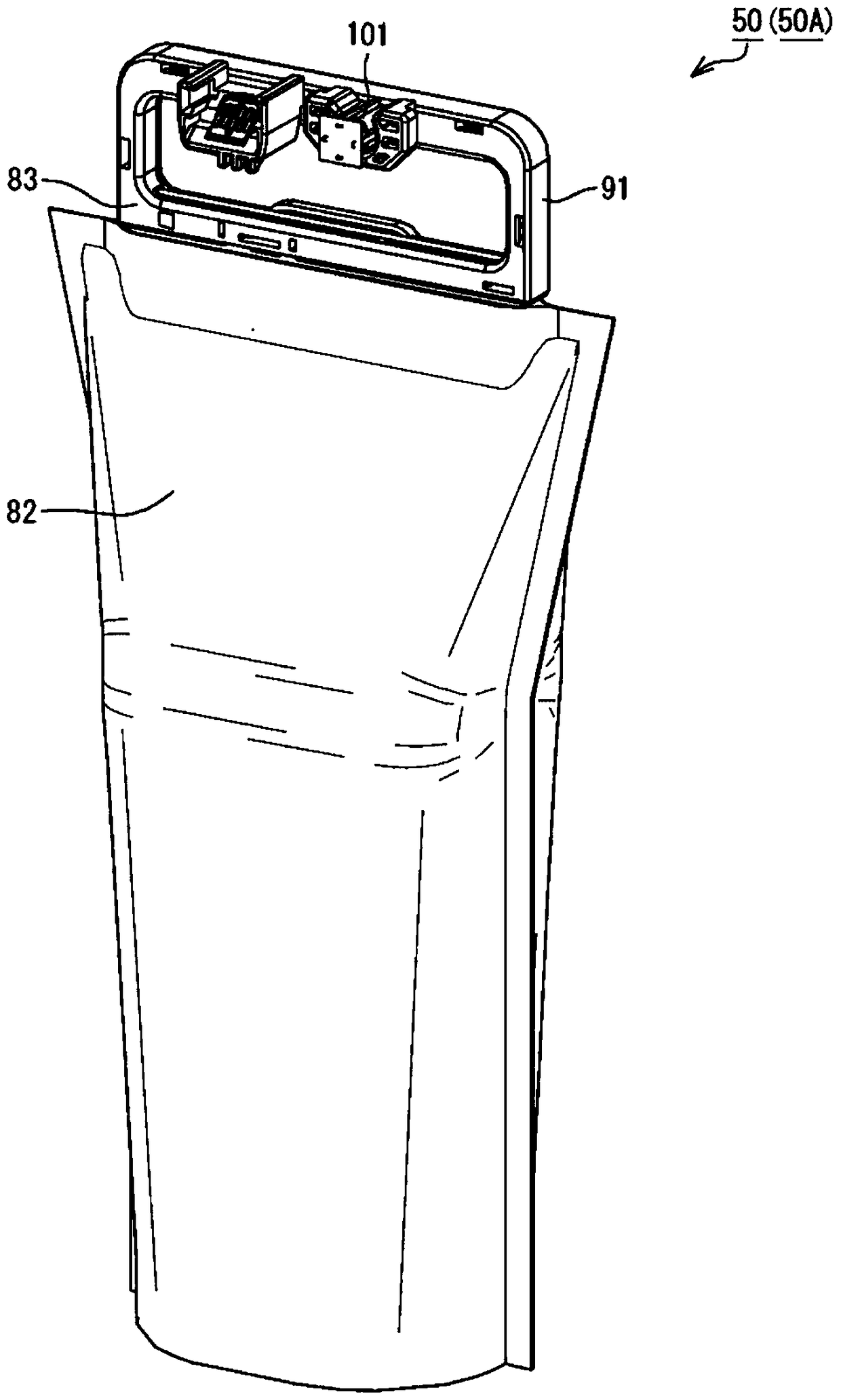
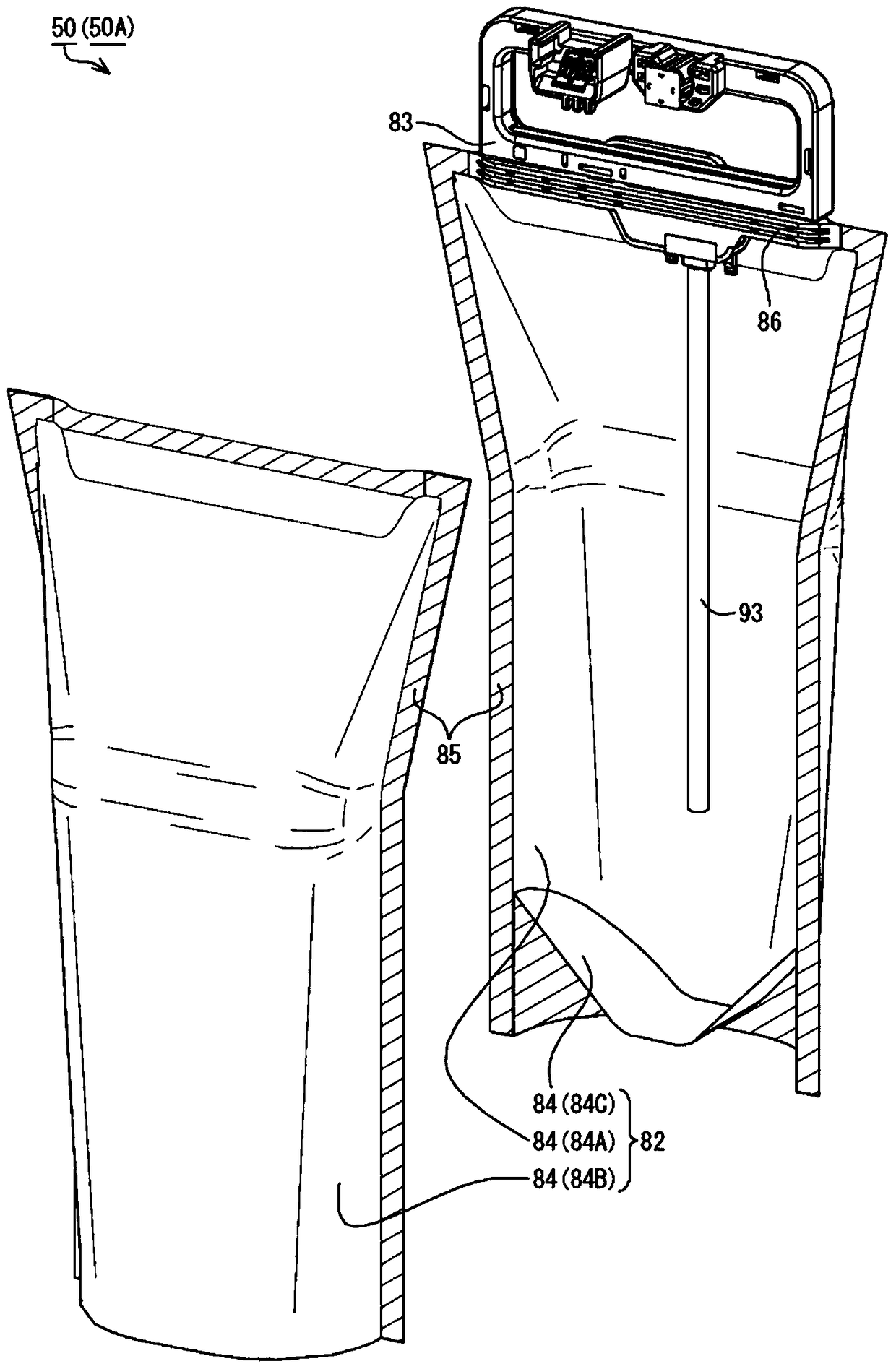
[0057] Such as figure 2 As shown, the ink container 50A of Example 1 has an ink container 82 as an example of a liquid container and a connection unit 83 . Such as image 3 As shown, the ink containing portion 82 has a structure in which a plurality of thin film members 84 having flexibility are joined to each other. In the ink storage portion 82, three film members 84 are bonded into a bag shape. In the ink storage portion 82 , when the three thin film members 84 are respectively identified, the three thin film members 84 are respectively indicated as a thin film member 84A, a thin film member 84B, and a thin film member 84C. The thin film member 84A and the thin film member 84B are welded to each other at the peripheral region 85 in a state where they overlap each other. The film member 84C is sandwiched between the film member 84A and the film member 84B. The periphery of the film member 84C is welded to the film member 84A and the film member 84B in a state overlappin...
Embodiment 2
[0095] Such as Figure 17 As shown, the ink container 50B of the second embodiment has an ink container 211 , an ink outlet unit 213 and an electrical contact unit 214 . In Embodiment 2, the same structures as in Embodiment 1 are assigned the same reference numerals as in Embodiment 1 and detailed description thereof is omitted. The ink container 211 has a bag-like structure in which a plurality of flexible film members 84 are joined together. A handle portion 215 is formed at an end portion of the ink storage portion 211 in the +Z-axis direction. An opening 216 is formed in the ink container 211 to penetrate the ink container 211 in the K1 direction. A portion of the ink storage portion 211 located on the +Z-axis direction side of the opening portion 216 constitutes a handle portion 215 .
[0096] This structure enables the operator to insert fingers into the opening portion 216 and hold the handle portion 215 . Then, the operator can lift the ink container 50B while hold...
Embodiment 3
[0102] Such as Figure 18 As shown, the ink container 50C of the third embodiment has an ink container 221 , an ink outlet unit 213 and an electrical contact unit 214 . In Example 3, the same structures as those in Example 1 and Example 2 are given the same reference numerals as in Example 1 and Example 2, and detailed description is omitted. The ink container 221 has a bag-like structure in which a plurality of flexible film members are joined together. A handle portion 223 is formed at an end portion of the ink storage portion 221 in the +Z axis direction.
[0103] In the ink storage portion 221 , a leg portion 224 is formed on the −Z-axis direction side of the handle portion 223 . The handle portion 223 is connected to the body portion 225 of the ink storage portion 221 via the leg portion 224 . The body part 225 , the leg part 224 and the handle part 223 are connected to form a bag-shaped ink storage part 221 . Therefore, not only the body portion 225 but also the hand...
PUM
 Abstract
Description
Claims
Application Information
 - R&D
- Intellectual Property
- Life Sciences
- Materials
- Tech Scout
- Unparalleled Data Quality
- Higher Quality Content
- 60% Fewer Hallucinations
Browse by: Latest US Patents, China's latest patents, Technical Efficacy Thesaurus, Application Domain, Technology Topic, Popular Technical Reports.
© 2025 PatSnap. All rights reserved.Legal|Privacy policy|Modern Slavery Act Transparency Statement|Sitemap|About US| Contact US: help@patsnap.com