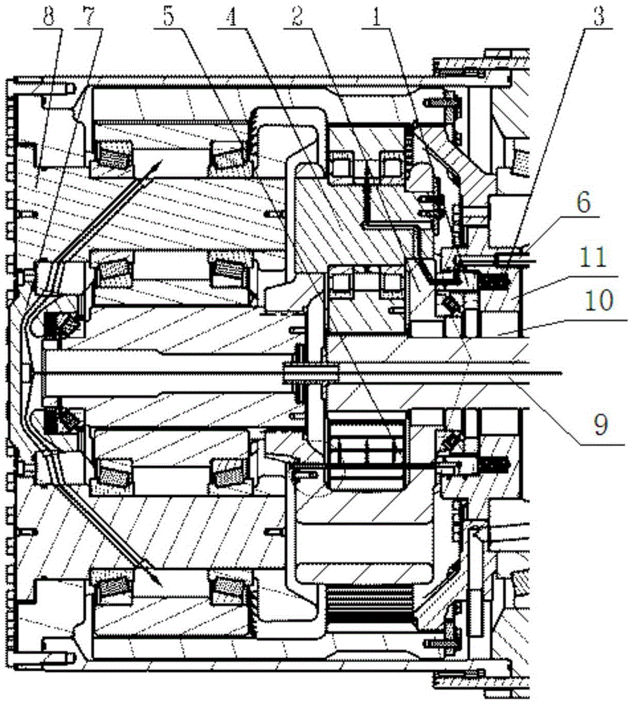
[0018] See Figure 1-3 , The embodiment of the present invention provides an adaptive lubrication structure for a reducer, which is connected to a hydraulic oil pump to lubricate the primary planet carrier 2 and the secondary planet carrier. The adaptive lubrication structure includes: a primary planetary gear lubrication device and Secondary planetary gear lubrication device.
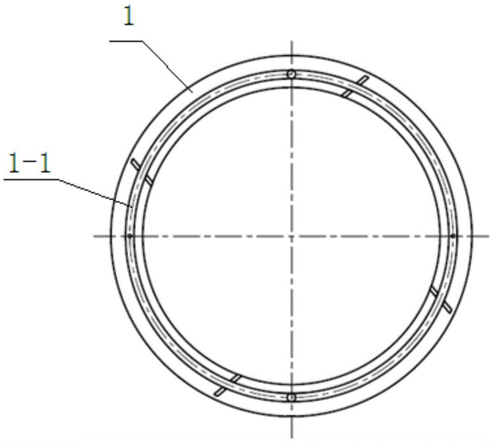
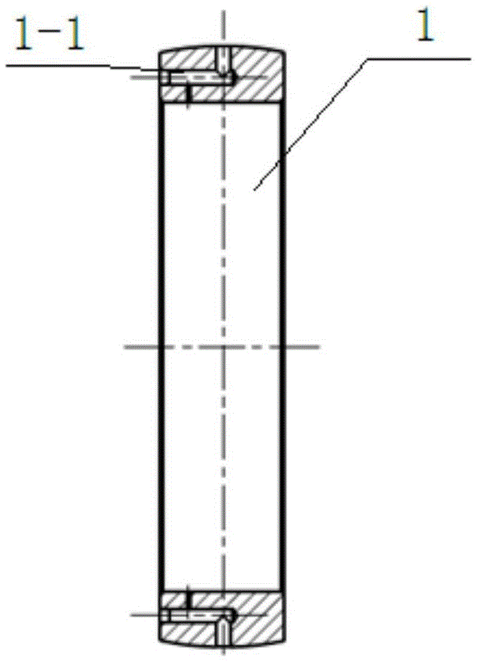
[0019] The first-stage planetary gear lubrication device includes: an oil inlet mechanism, an oil guide bracket 1, a support bearing 11, a pre-tensioning mechanism, and an oil return mechanism. One end of the oil inlet mechanism is in communication with the hydraulic oil pump, and the other end is connected with the guide The oil support 1 is in communication, one end of the oil guide support 1 is in contact with the end surface of the first stage planet carrier 2, the oil guide support 1 is provided with an annular oil groove 1-1, and one end of the pre-tensioning mechanism is connected to the oil guide support 1 is connected, the other end is connected to the support bearing 11, and the oil return mechanism is arranged under the oil guide bracket 1.
[0020] One end of the secondary planetary gear lubrication device is in communication with the hydraulic oil pump, and the other end is in communication with the secondary planet carrier.
[0021] Wherein, the lubricating oil of the hydraulic oil pump enters the oil guide bracket 1 through the oil inlet mechanism, and the annular oil groove 1-1 of the oil guide bracket 1 is opposed to the primary planet carrier pin of the primary planet carrier 2. 4 and the nozzle 5 separate oil, the pre-tensioning mechanism presses the oil guide bracket 1 on the end surface of the first-stage planetary carrier 2 through the support bearing 11, and the lubricating oil produces a reaction force on the pre-tensioning mechanism to make The end surface of the first-stage planet carrier 2 and the end surface of the oil guide bracket 1 are separated by an oil film. When the flow rate of the lubricating oil of the hydraulic oil pump exceeds the design flow range, the reaction force increases, which is greater than the pre-tightening force. The oil guide bracket 1 is pushed open, excess lubricating oil overflows, and is recovered by the oil return mechanism. The hydraulic oil pump lubricating oil passes through the secondary planetary gear lubrication device to the secondary planetary carrier column of the secondary planetary carrier. Pin 8 is lubricated.
[0022] The structure of the oil inlet mechanism is introduced in detail.
[0023] The oil intake mechanism includes: an oil pipe support 6.
[0024] One end of the oil pipe support 6 communicates with the hydraulic oil pump, and the other end communicates with the oil guide support 1. The lubricating oil in the hydraulic oil pump enters the oil guide support 1 through the oil pipe support 6.
[0025] The structure of the pre-tensioning mechanism is introduced in detail.
[0026] The pre-tensioning mechanism includes: a spring 3.
[0027] One end of the spring 3 is fixedly connected to the oil guide bracket 1. Specifically, in this embodiment, one end of the spring 3 is fixedly connected to the oil guide bracket 1 by a bolt. In other embodiments, one end of the spring 3 can be connected to the oil guide bracket 1 by other means such as a shaft pin. The bracket 1 is fixedly connected. The other end of the spring 3 is fixedly connected to the support bearing 11. Specifically, in this embodiment, the other end of the spring 3 is fixedly connected to the support bearing 11 through a bolt. In other embodiments, the other end of the spring 3 can be connected to the support through other means such as a shaft pin. The bearing 11 is fixedly connected. The spring force formula is F=6KX, where K refers to the stubborn coefficient of the spring, also called the elastic coefficient. X refers to the elongation of the spring; the pressure formula of the lubricating oil on the oil guide bracket: H=PXS, P Indicates the pressure, S is the pressure area of the oil guide bracket.
[0028] The structure of the oil return mechanism is introduced in detail.
[0029] The oil return mechanism includes: an oil return pipeline 10.
[0030] The oil return pipeline 10 is fixedly arranged under the oil guide bracket 1. Specifically, in this embodiment, the oil return line 10 is fixedly arranged under the oil guide bracket 1 by bolts. In other embodiments, the oil return line 10 may be fixedly arranged by other means such as shaft pins. Below the oil guide bracket 1.
[0031] The structure of the secondary planetary gear lubrication device is introduced in detail.
[0032] The secondary planetary gear lubrication device includes: an oil inlet pipe 9 and a thrust bearing bracket 7.
[0033] The oil inlet pipe 9 is in communication with the hydraulic oil pump, and the oil inlet pipe 9 receives the lubricating oil of the hydraulic oil pump.
[0034] One end of the thrust bearing bracket 7 is in communication with the oil inlet pipe 9 and the other end is in communication with the secondary planet carrier. The lubricating oil enters the thrust bearing bracket 7 through the oil inlet pipe 9 and passes through the thrust The bearing bracket 7 enters the secondary planet carrier.
[0035] Based on the same inventive concept, the present invention provides an adaptive lubrication method for a reducer including the following steps:
[0036] Step 1, the lubricating oil of the hydraulic oil pump enters the oil guide support 1 through the oil pipe support 6 of the oil intake mechanism.
[0037] Step 2: The annular oil groove 1-1 of the oil guide bracket 1 separates oil from the primary planetary carrier pin 4 and the nozzle 5 of the primary planetary carrier 2.
[0038] Step 3. The spring 3 of the pre-tensioning mechanism presses the oil guide bracket 1 on the end surface of the first-stage planet carrier 2 through the support bearing 11, and the lubricating oil produces a reaction force on the spring 3 to make the one The end surface of the stage planet carrier 2 and the end surface of the oil guide bracket 1 are separated by an oil film.
[0039] Step 4. When the flow rate of the lubricating oil of the hydraulic oil pump exceeds the design flow range, the reaction force will increase, which is greater than the pre-tightening force. The oil guide bracket 1 will be pushed open, and the excess lubricating oil will overflow. The oil return line 10 of the oil mechanism is retracted.
[0040] Step 5: The hydraulic oil pump lubricating oil lubricates the secondary planetary carrier pin 8 of the secondary planetary carrier through the secondary planetary gear lubrication device.
[0041] Step 3 is described in detail.
[0042] The spring force formula is F=6KX, where K refers to the stubborn coefficient of the spring, also called the elastic coefficient. X refers to the elongation of the spring; the pressure formula of the lubricating oil on the oil guide bracket: H=PXS, P Indicates the pressure, S is the pressure area of the oil guide bracket. The spring force is balanced with the pressure of the lubricating oil on the oil guide bracket 1.
[0043] Step 5 is described in detail.
[0044] The secondary planetary gear lubrication device includes: an oil inlet pipe 9 and a thrust bearing bracket 7.
[0045] The oil inlet pipe 9 is in communication with the hydraulic oil pump, and the oil inlet pipe 9 receives the lubricating oil of the hydraulic oil pump.
[0046] One end of the thrust bearing bracket 7 is in communication with the oil inlet pipe 9 and the other end is in communication with the secondary planet carrier. The lubricating oil enters the thrust bearing bracket 7 through the oil inlet pipe 9 and passes through the thrust The bearing bracket 7 enters the secondary planet carrier.
[0047] In order to introduce the embodiments of the present invention more clearly, the following describes the usage methods of the embodiments of the present invention.
[0048] The lubricating oil from the hydraulic oil pump enters the oil pipe support 6, and the lubricating oil in the oil pipe support 6 is separated by the oil guide support 1. The oil guide bracket is stationary, and the primary planetary bracket 2 rotates together with the reducer housing. Since the oil guide bracket is provided with an annular oil groove 1-1, the three primary planetary bracket pins 4 on the primary planetary bracket 2 can be real-timely aligned. The oil is separated from the three nozzles 5, and the multi-point lubrication is realized through the annular oil groove 1-1 of the oil guide bracket 1. Thus, the three primary planetary gears and the bearings of the primary planetary gear are simultaneously lubricated. There are six springs 3 between the oil guide bracket 1 and the support bearing 11 to press the oil guide bracket 1 on the end surface of the primary planet carrier 2. There is a lubricating oil passage between the oil guide bracket 1 and the primary planet carrier 2. Lubricated oil tank. When the reducer is running, the first stage planet carrier 2 will rotate, and the lubricating oil from the oil pipe support 6 will pass through the oil groove of the oil guide bracket 1. At this time, the lubricating oil will have a reaction force on the spring 3, making the end surface of the first stage planet carrier 2 The end surface of the oil guide bracket 1 is separated by an oil film, and the lubricating oil at the oil groove is used to lubricate the end surfaces of the oil guide bracket 1 and the first-stage planet carrier 2. The spring force formula is F=6KX, where K refers to the stubborn coefficient of the spring, also called the elastic coefficient. X refers to the elongation of the spring; the formula for the pressure of the lubricating oil on the oil guide bracket: H=PXS, P represents the pressure , S is the pressure area of the oil guide bracket. It can be seen from the above formula that the spring is selected through reasonable calculation, so that the force between the lubricating oil reaction force and the spring force can reach a certain balance, and the lubrication pipeline for the first-stage planetary gear is guaranteed to be unblocked. When the hydraulic oil pump flow exceeds the design flow range, the reaction force will increase, which is greater than the spring force, the oil guide bracket is pushed open, the excess lubricating oil overflows, and is retracted through the oil return line below, thus ensuring a certain flow of lubrication. The action of the spring 3 adapts to the change of the oil volume, and overflows the excess oil volume directly into the oil return pipe from below to ensure the continuous and reliable lubricating oil. Lubricate the secondary planetary gears: the lubricating oil of the hydraulic oil pump enters the thrust bearing bracket 7 through the middle oil inlet pipe 9 and then passes through the secondary planetary bracket pin 8 to lubricate the three secondary planetary gears and bearings respectively.
[0049] Finally, it should be noted that the above specific embodiments are only used to illustrate the technical solutions of the present invention and not to limit them. Although the present invention has been described in detail with reference to examples, those of ordinary skill in the art should understand that the technical solutions of the present invention can be implemented Modifications or equivalent replacements, without departing from the spirit and scope of the technical solution of the present invention, shall be covered by the scope of the claims of the present invention.